The Telefunken RA 770 Analog Computer
|
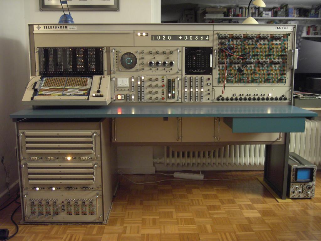
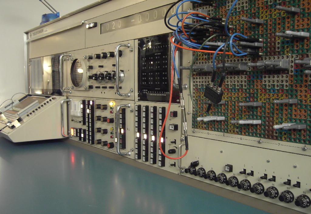
On November 14th, 2007, a dream back from days of childhood came true, when I became the very, very happy and proud owner of a wonderful Telefunken RA 770 analog computer which can be seen after restoring and repair in the picture above. The RA 770 is, in my opinion, the finest analog computer ever made by any manufacturer - it is a high precision analog computer (10^-4) in the very best tradition of Telefunken which can be seen in every detail of the system. I would like to thank Mr. Flaskamp from the Forschungszentrum Jülich who saved this wonderful machine from scrap and gave me a phone call asking if I were interested in the system. Without his invaluable support the system would have been scrapped. Also, I would like to thank Mr. Fiss from the Bundesfinanzministerium for his help with some formal aspects. On November 14th, 2007, my beloved wife Rikka and I were on our way with a truck to Jülich to get the machine. Mr. Flaskamp and his coworkers did a grand job in loading the rather heavy system which was partially dismantled in our truck (the system weighs about 550 kg). |
|||||||||||||
|
Restoring and repairing the machine: |
|||||||||||||
|
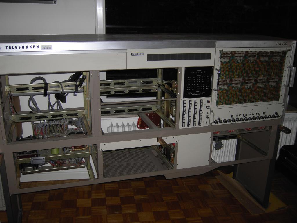
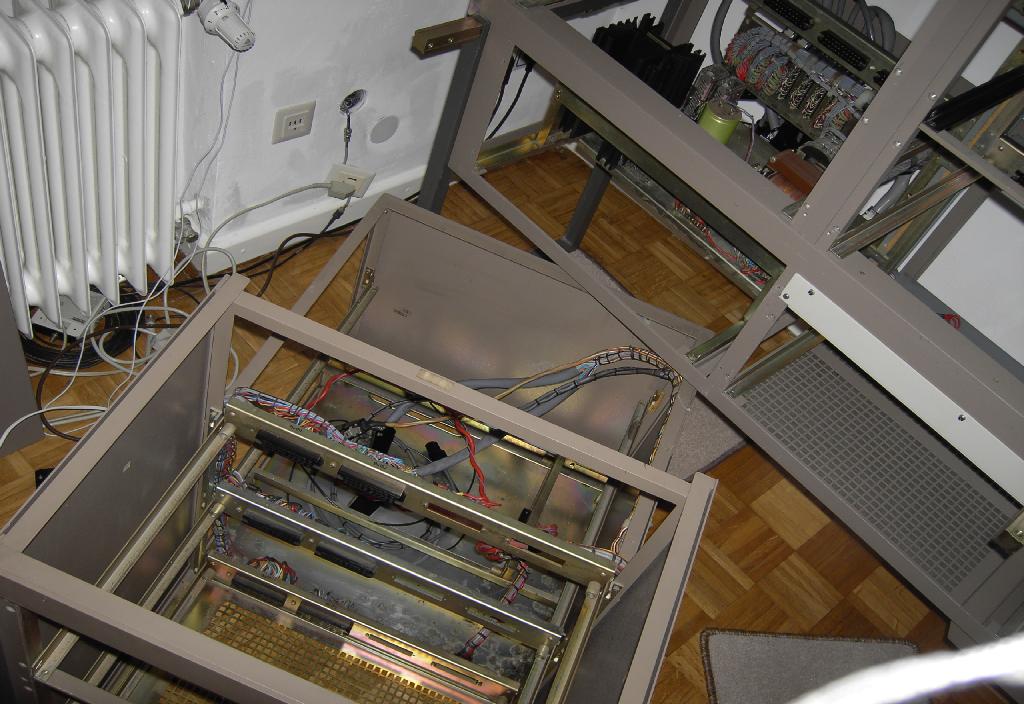
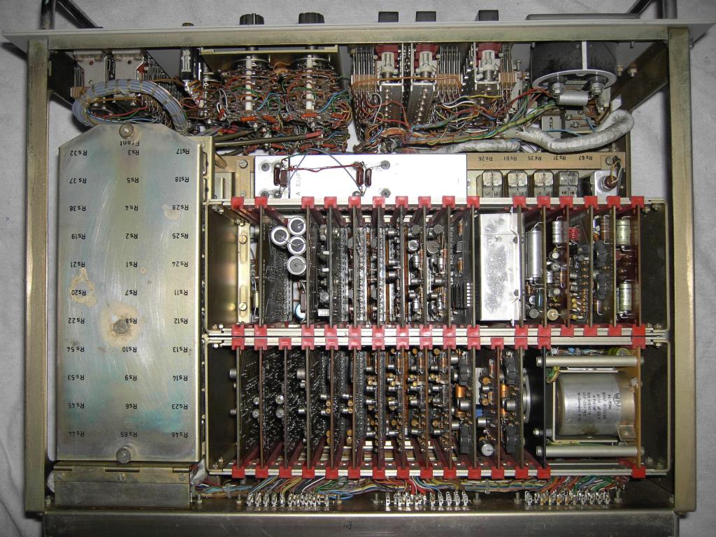
The picture on the left shows the nearly empty main frame of the RA 770 after it arrived at home (without the help of my friends Joachim Wagner, Dr. Christian Kaminski and, of course Rikka it would not have been possible to get the frame into the house. Prior to transporting the system we removed all drawers as well as all printed circuit cards and cabling as far as possible to get the weight of the frame down and to minimize the risk of damaging something during the transport. |
||||||||||||
|
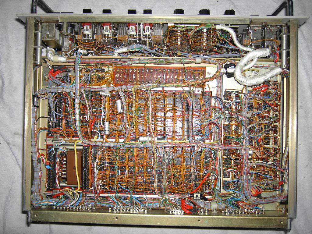
On the right, the subframe UBE 770 can be seen - normally it is located on the lower left of the main frame and houses two to three extension drawers containing function generators, non linear networks and the like. This frame has been removed, too, to facilitate the transport of the system. It was obvious that quite some mice have been living in the system when we looked at the UBE 770 in more detail. There was an incredible amount of dirt covering all and everything and it became clear that the first action to be taken was to clean every single part of the system thoroughly and then inspect it for damage due to its inhabitants. |

|
||||||||||||
|
The result of the first cleaning efforts can be seen on the left - we were afraid that this might only be the beginning of a rather disgusting work dealing with incredible amounts of mice droppings and the like and we were right. |
||||||||||||
|
The picture on the right shows the first impression we had after removing the top panels from the machine. Nearly everything was covered with mice droppings and felt sticky and smelled rather bad to say the least. |
|
||||||||||||

|
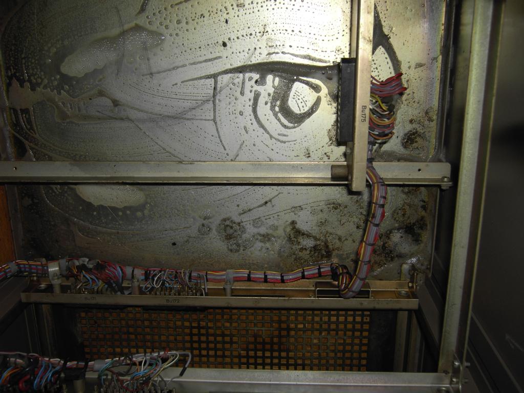
The true amount of the problem became obvious at the central relais frame which is located in the middle of the machine and contains a variety of control relays for the overall operation of the system. It turned out that the mice droppings were not easily removed since they were quite sticky and left a disgusting residue on everything they were placed on, so I began to pick them one after the other with tooth picks out of the circuitry. After this I would clean the area with detergents. |
||||||||||||
|
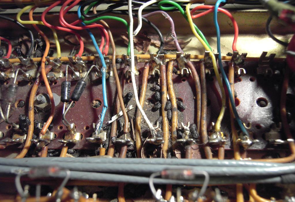
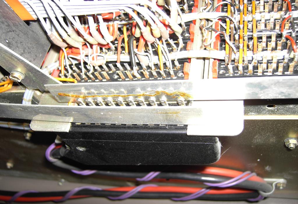
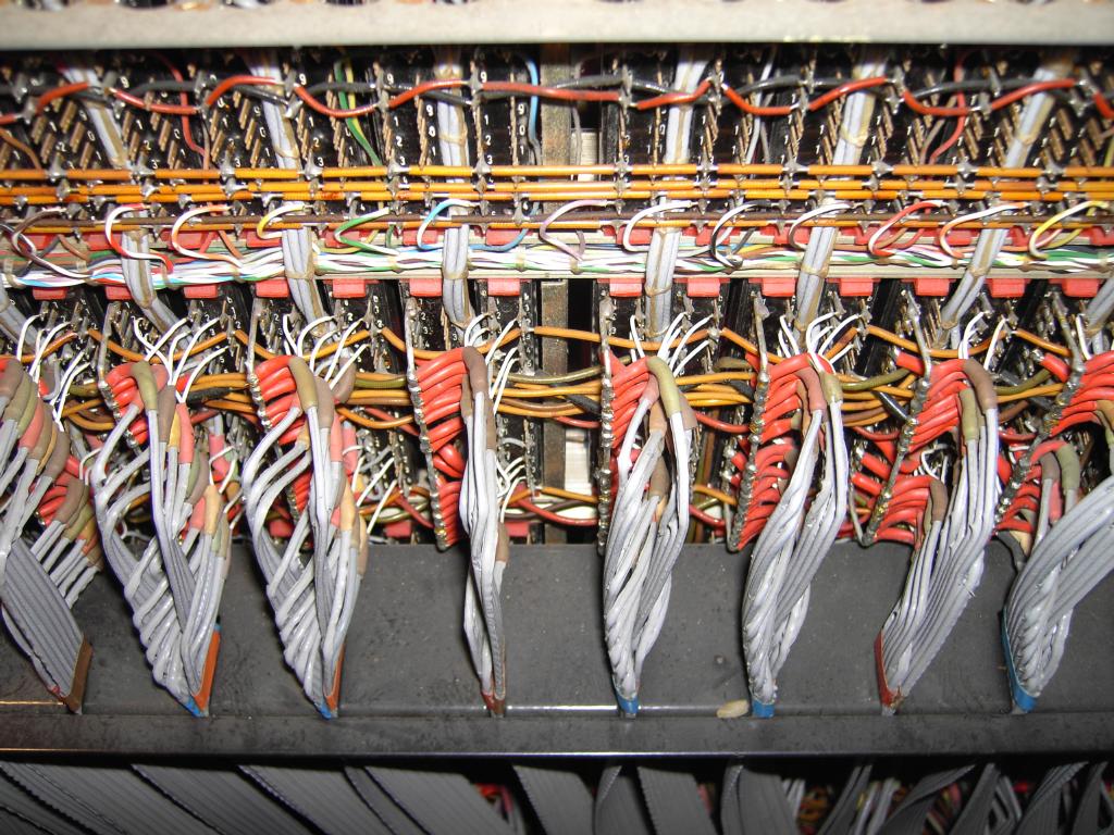
Unfortunately the mice had found that the insulation of the wiring of the machine tasted good and started to chew through some wires which can be seen in the picture on the right. Fortunately all of the wires which were cut through were easily replaced since the mice were kind enough to let some traces of both ends of the wires intact so with a bit of guessing and the occasional help of the fantastic circuit schematics from Telefunken it was just a matter of time to fix the damages done by the mice. |
|
||||||||||||

|
One of the most time consuming (and most disgusting) problems is shown in the picture on the left. These are the card guiding slides which were frequently used by the mice to, ... To resolve this problem the card cages had to be completely dismantled since it proved next to impossible to clean the slides without removing them from the card cage. |
||||||||||||
|
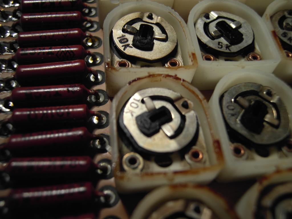
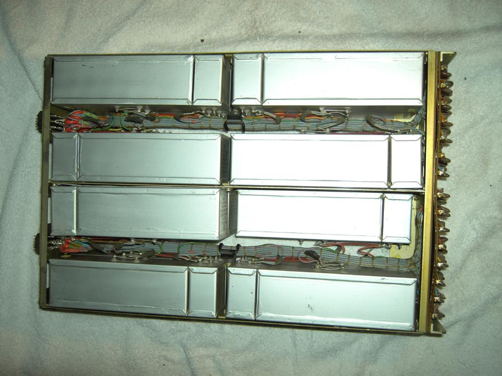
During dismantling the card cages it became clear that the mice excrements found their way to the board seated in the card cages causing corrision on contacts and finding its way into the sealed potentiomter housings of the parabola function generators of the multipliers. The picture on the right shows part of such a parabola function generator with the lid of the protective potentiometer housing removed for cleaning. Since the settings of the potentiometers are crucial for the operation of the multipliers the process of cleaning them was very delicate and time consuming. |
|
||||||||||||
|
|
||||||||||||
|
The two pictures above show the process of reattaching the UBE 770 expansion frame to the main frame of the RA 770 analog computer. Attaching the three interconnect cables to the main frame required some detective work since these seemed to be the only cables which were not properly labeled, but fortunately their wiring matched with only one receptable on the main frame, each. |
|||||||||||||
|
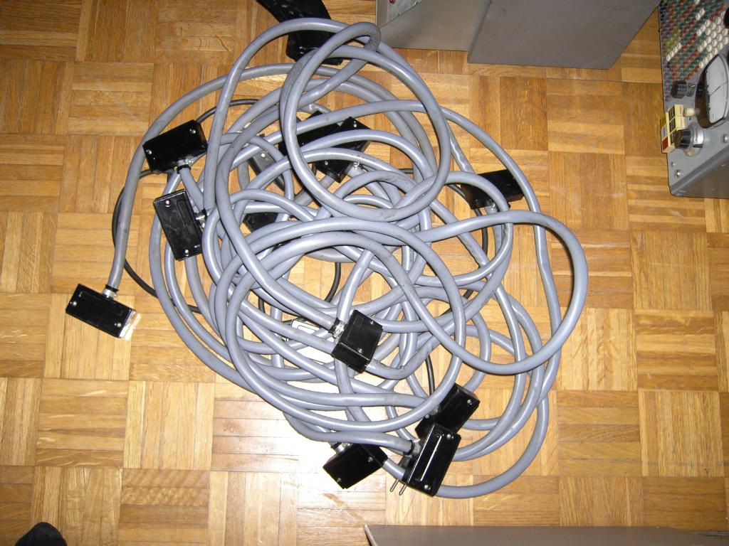
The picture on the left shows the six additional interconnect cables which carry signals between the main frame and the three drawers to be installed in the UBE 770 expansion frame. |
||||||||||||
|
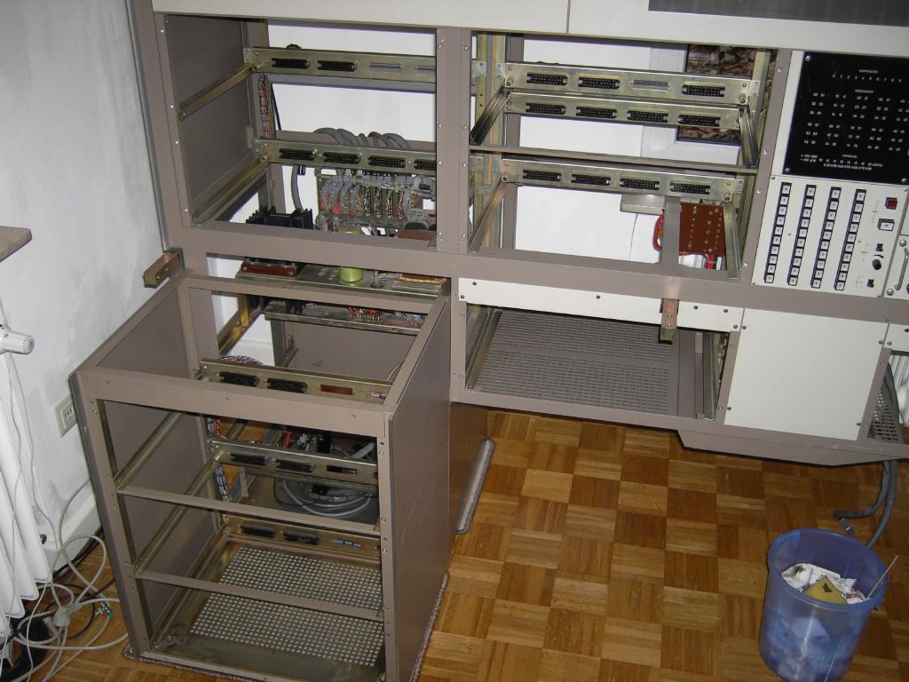
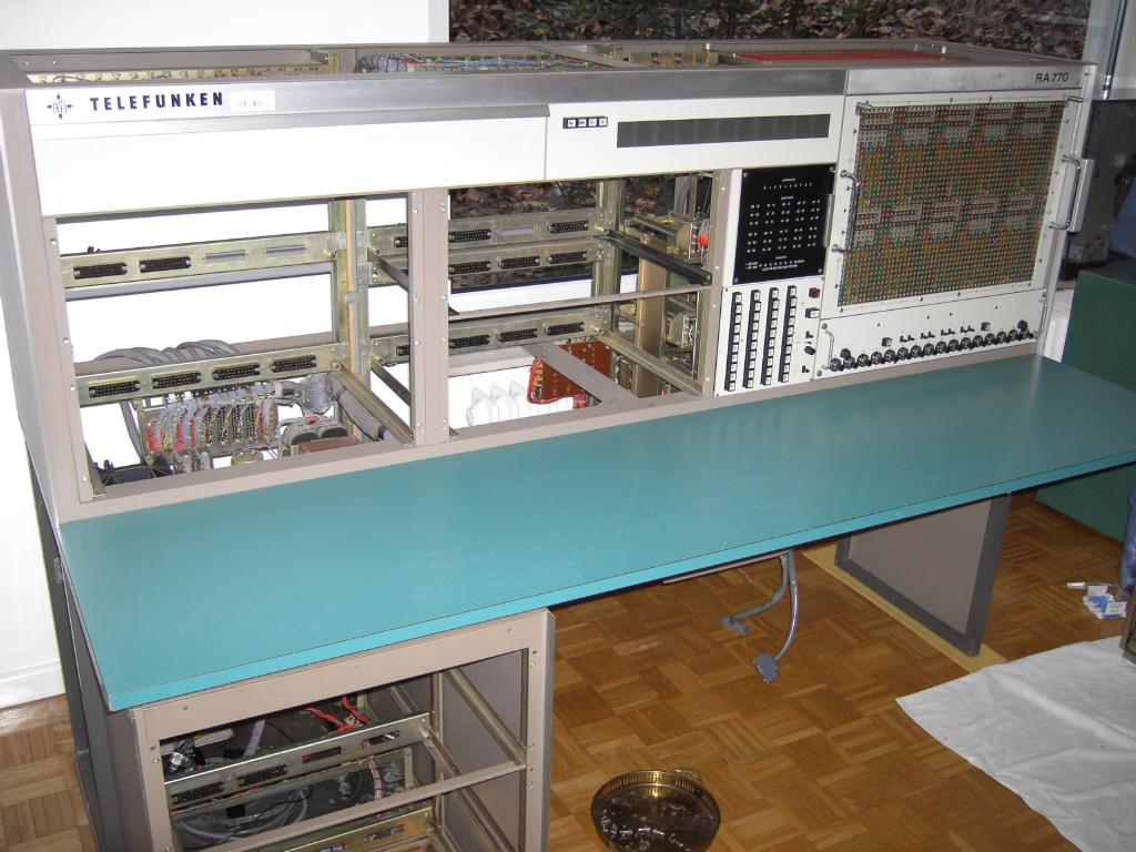
The picture on the right shows the completed frame of the machine after cleaning, repairing the broken wires and reattaching the expansion fram UBE 770. |
|
||||||||||||
|
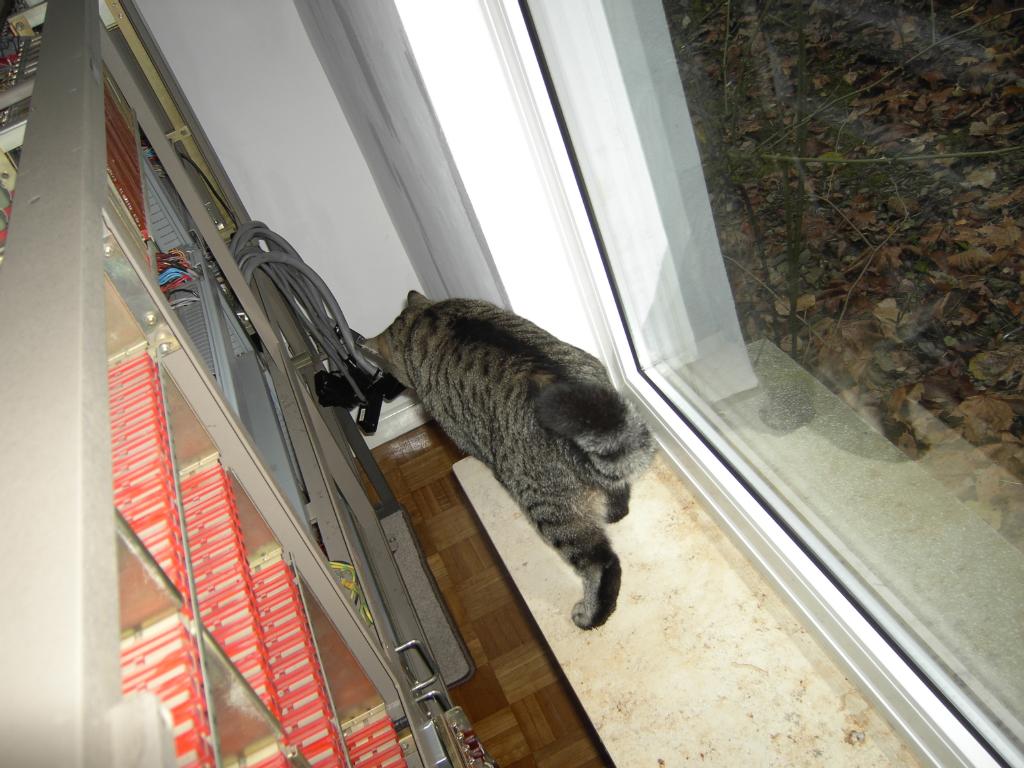
All of this cleaning and repair work was very interesting not only for me but for Streifchen, the cat, as well. He did his very best to be of assistance but could not find any surviving mice - I am sure he would have saved the machine from their rampage if he had been there in time. |
|||||||||||||
|

|
||||||||||||
|
Subassemblies:The following section shows the various subassemblies which are part of the RA 770 analog computer. |
|||||||||||||

|
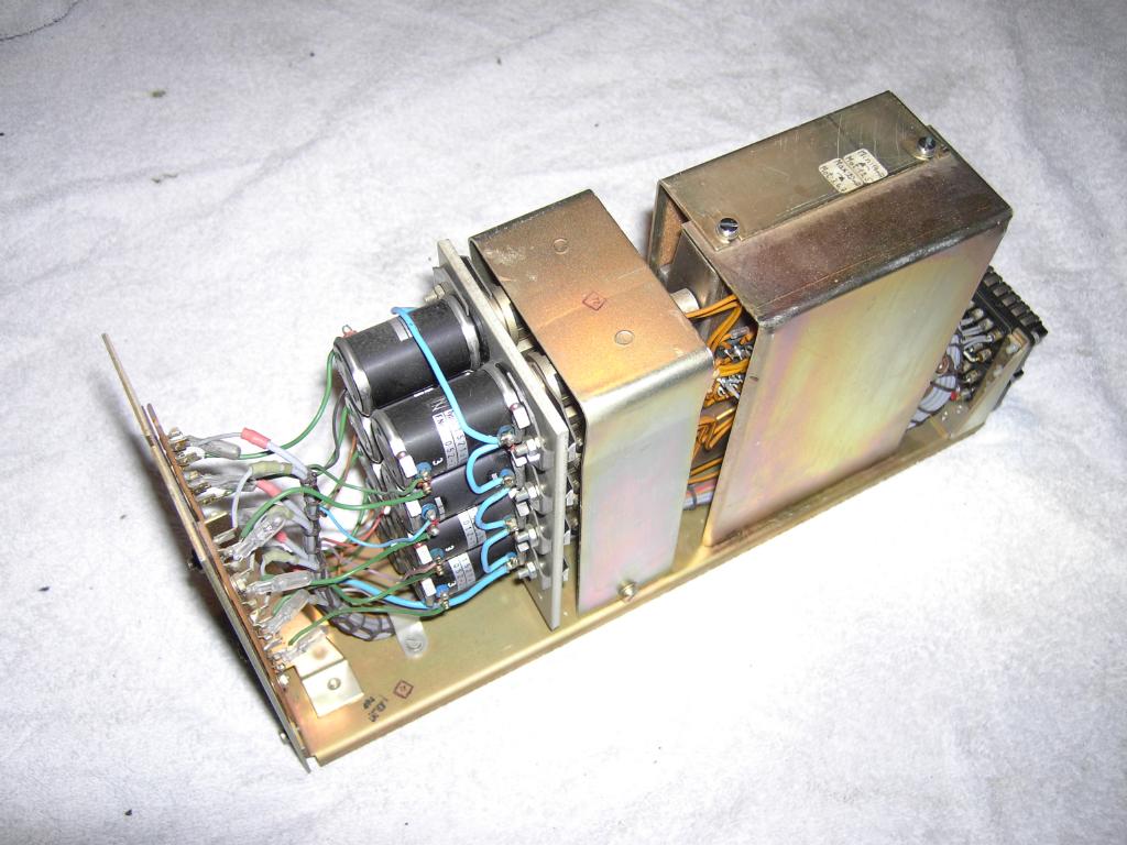
The picture on the left shows one of the two power supplies - this one contains the power distributors for the line voltage, the usage counter, the mains fuses and delivers -25 V (for powering relays) and 6 V AC and 10 V AC (for display lights). Only the -25 V supply is stabilized - the power transistors are mounted on the large cooling fin on the left. |
||||||||||||

|

|
||||||||||||
|
The two pictures above show the top and bottom view of the second power supply, the STV 771. This power supply delivers the following voltages:
The top view of the power supply shows the two main transformers on the top of the picture as well as the vast amount of coils to smooth the voltages prior to feeding the regulators. The relays visible on the bottom of the picture detect overcurrent conditions and protect the output stages as well as display the error condition on a central display field. |
|||||||||||||
|
|
||||||||||||
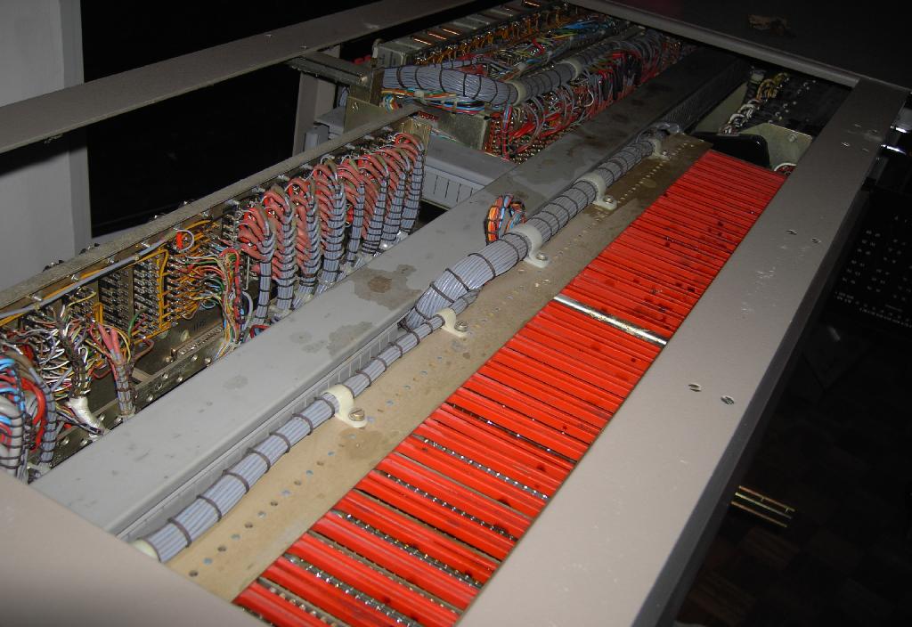
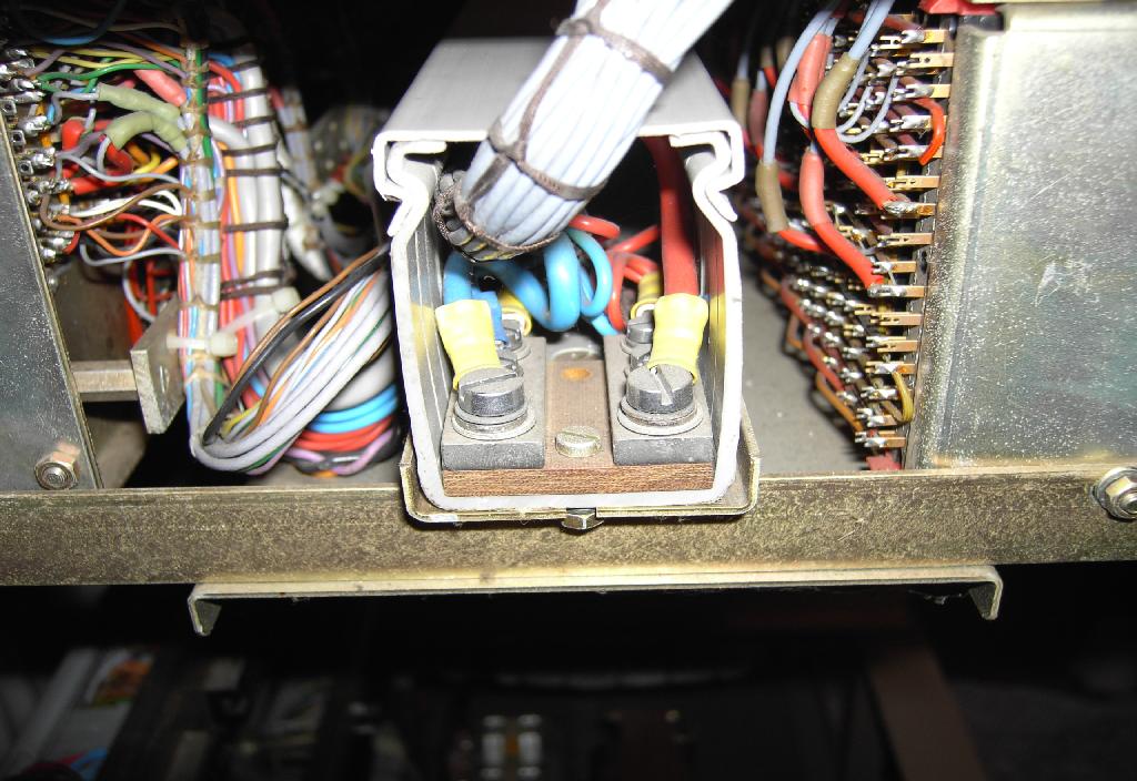
| The two pictures above give an impression of the power distribution system of the RA 770 - although the currents of the various computing elements are very small (only several mA each) the power distribution bars are of a large diameter to avoid unnecessary voltage drops. Of course there is a central ground point in the machine since ground loops would be fatal for the overall accuracy of the system. The various different ground lines (relay ground, chopper ground, high precision ground etc.) are combined only at this common ground block. | |||||||||||||
|
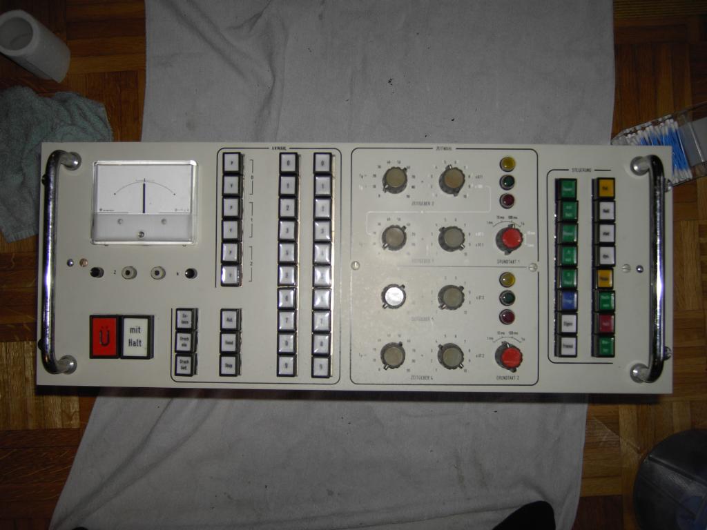
On the right the front panel of the central control drawer, the DBG 771 (Digitales Bediengerät) can be seen. It is divided into three parts (from left to right):
|
|
||||||||||||
|
|
||||||||||||
|
The two pictures above show the top and bottom of the DBG 771 - obviously it is the single most complex part of the RA 770. It contains all of the digital stages necessary to generate the various clock signals needed for controlling the integrators and track/store circuits as well as the quite complex mode control logic which is implemented largely using relays. |
|||||||||||||
|
The picture on the left shows a rather unusual feature for an analog computer: This card contains the oven stabilized main quartz oscillator which serves as the base for all clock signals derived from its output. Most analog computers just use a precision integrator as the main clock, but not the RA 770. Since it is often convenient to have a time proportional ramp signal during a calculation to drive an oscilloscope or a plotter it also features such a precision integrator but its only purpose is to generate a time proportional deflection voltage. |
||||||||||||
|
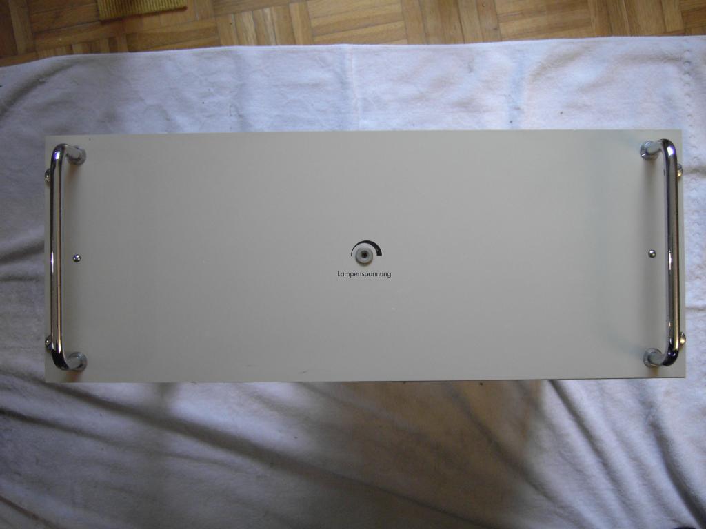
The system incorporates a central high precision digital voltmeter which can be connected under the control of the control unit DBG 771 to the output of any active computing component of the RA 770. This device, the DVM 791, is shown on the right. It has not display itself since it only drives the central readout display which can be seen quite good in the very first picture of this page. The adjustment screw in the middle of the front plate controls the voltage regulator which supplies the incandescent display lights. |
|
||||||||||||
|
|
||||||||||||
| The pictures above show the top and bottom view of the precision digial voltmeter DVM 791. Obviously it is not too populated which is due to the fact that Telefunken once decided to stop building its own precision digital voltmeters which were based on the technique of successive approximation. Instead it was decided to use an off the shelf high precision digital voltmeter from another vendor and surround this with the necessary circuitry to maintain the same external interface as the old DVM. | |||||||||||||
|

|
||||||||||||
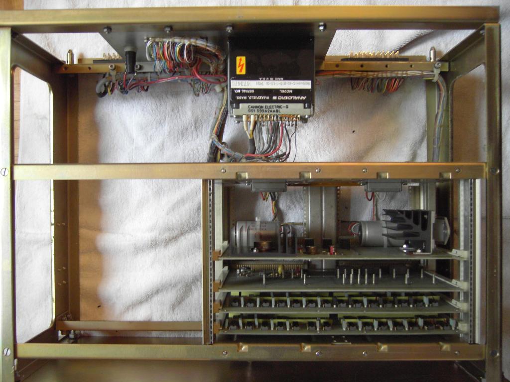
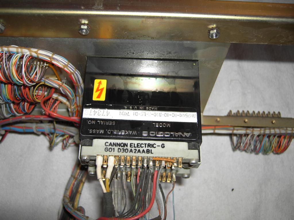
| This OEM digital voltmeter (made by ANALOGIC) can be seen in the pictures above. It is based on the technique of dual slope integration and has a precision of 0.01 percent. | |||||||||||||
|
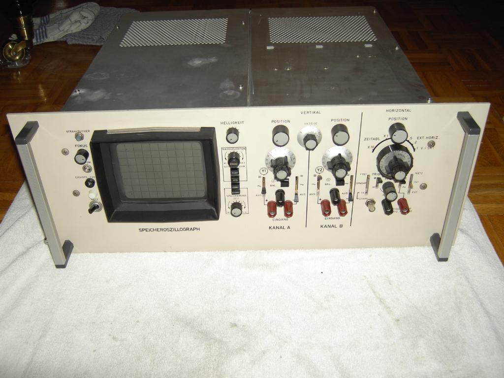
Around 1970 Telefunken decided to abandon its own line of specialized dual trace oscilloscopes specially developed for its line of analog computers (the OMS 811 oscilloscop) and to repackage a dual channel analog storage oscilloscope made by HP. This device was then named HPO 771 and used in conjunction with the RA 770 analog computer. Its front plate can be seen on the left - since the standard Telefunken drawer is a bit larger than the 19 inch usual today it looks a little bit awkward and is not a prefect optical match for the wonderful RA 770. Unfortunately my HPO 771 has a severe problem in its high voltage power supply which I until now was unable to fix (due to the lack of schematics, mainly). Therefore I decided to insert one of my two OMS 811 oscilloscopes which were used in this machine, too. |
||||||||||||
|
|
||||||||||||
|
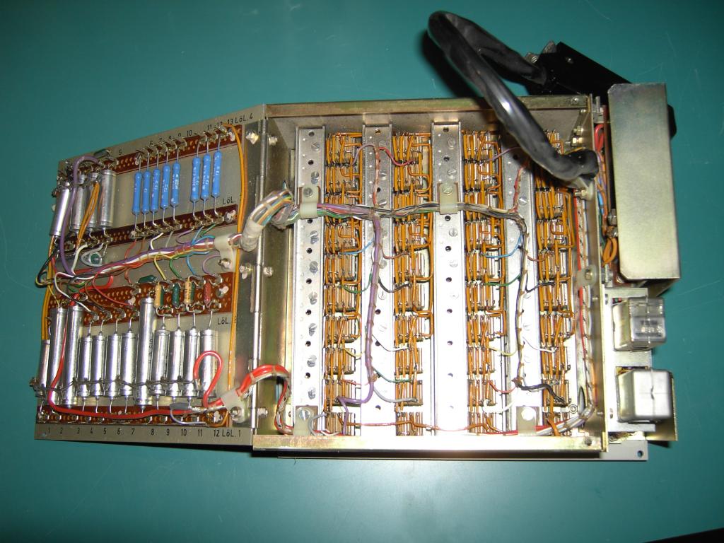
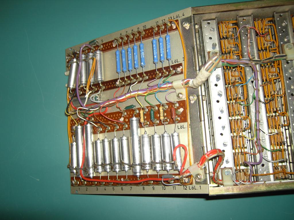
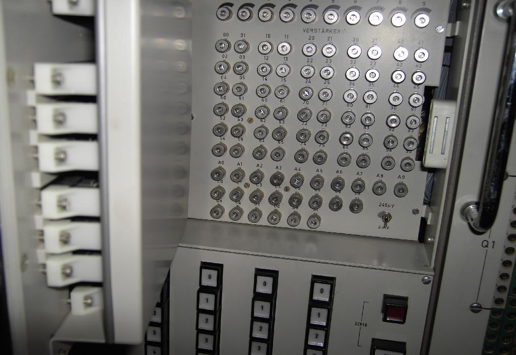
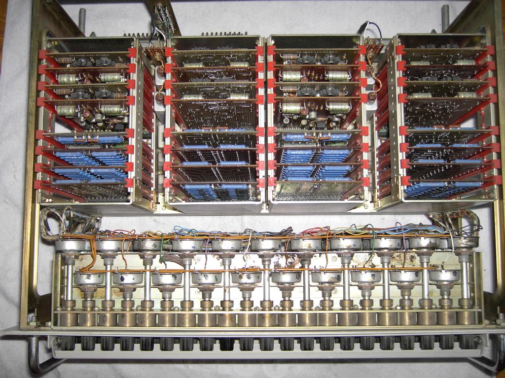
The next part of the system covered here are the servo potentiometers which are used in the RA 770. The basic idea is to have a central keyboard on which coefficient values can be entered with a precision of four decimal digits. This value is then set by a servo loop consisting of a small motor coupled to a precision potentiometer and some servo electronics. This keyboard can be seen in the overal picture of the machine on the top of this page between the DBG 771 and the analog patch field. The two pictures above show the interiors of this coefficient setting unit. It consists of some high precision voltage dividers which are connected to four sets of ten keys each generating an output voltage between 0.0000 and 0.9999 machine units (10 V). Please note that the precision resistors on the bottom left of are shielded! |
|||||||||||||
|
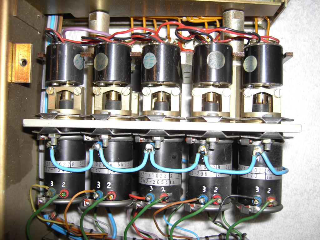
The picture on the right shows one of seven servo potentiometer units used in this RA 770. These units consist of 10 or 9 (depending on the model) potentiometers with their associated motors, a small gear and a clutch. |
|
||||||||||||
|
|
||||||||||||
|
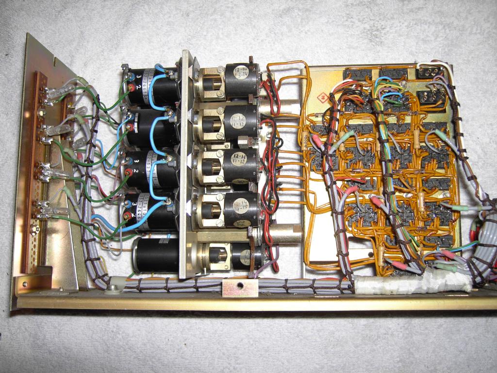
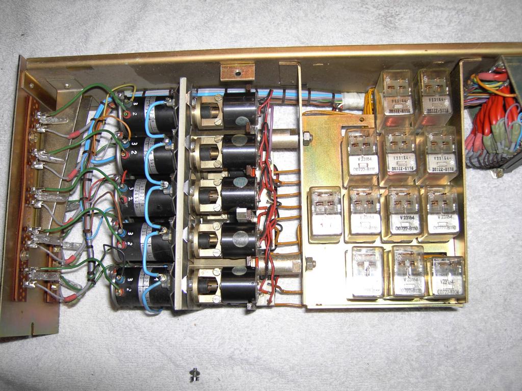
The two pictures above show the left and right side view of such a servo potentiometer unit with the shielding removed. |
|||||||||||||
|
On the left a detailed view of the innards of such a servo potentiometer drawer can be seen. The potentiometers are located on the bottom while the miniature motors with their associated gears are on the top. Between motors and potentiometers is a simple slip clutch to avoid damage to the potentiometers in case of a faulty servo loop. |
||||||||||||

|

|
||||||||||||
|
The pictures above show some of the servo potentiometer drawers installed in the computer. |
|||||||||||||
|
Visible on the right is the panel holding the potentiometers for the zero adjustment of the operational amplifiers of the main frame. This panel is located behind the central overload indicator panel (see the first picture of this page, next to the analog patch panel). |
|
||||||||||||
|
On the left the digital expansion drawer is shown. Nearly every large scale analog computer built after about 1965 featured a collection of some basic digital logic elements which could be used to individually control single integrators during complicated computations etc. This was often used in optimization problems and the like where decisions had to be performed and parameters had to varied automatically. These digital expansion groups are normally programmed like their analog counterparts by patching the desired connections between the logic elements needed for a computation. This digital patch field can be seen on the bottom of the DZ 772. On top is the card cage holding some logic circuit boards. |
||||||||||||

|

|
||||||||||||
| The two pictures above show the top and bottom of the DZ 772 logic expansion group during the cleaning phase. | |||||||||||||
|
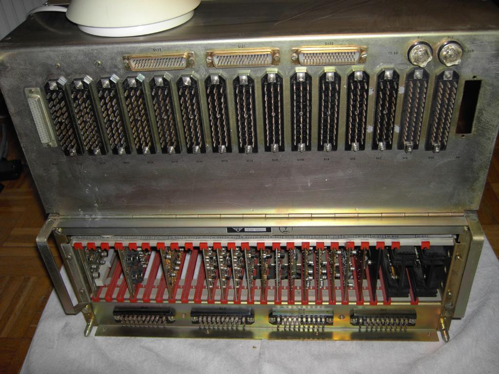
The rear of the DZ 772 is shown on the right. Since it is one of the central control instances of the RA 770 analog computer (apart from the DBG 771) it has a lot of connections going to nearly every part of the system. |
|
||||||||||||

|
The expansion frame UBE 771 allows the installation of additional drawers like the NNT 771 containing non linear networks. Part of its front plate can be seen in the picture on the left. This drawer may contain up to eight function generators with a total of 24 additional operational amplifiers which may be used as stand alone inverters or in conjunction with the non linear networks. Due to the complexity of the networks and the possibility to use this drawer with smaller Telefunken analog computer systems, too, its front plate contains eight small analog patch fields. |
||||||||||||
|
|
||||||||||||
| The two photos above show the top and bottom view of the NNT 771 drawer. In the middle are two card cages holding 12 operational amplifiers each with some control circuitry. The two outer cages can be populated with function generator cards. This particular NNT 771 only contained the 24 operational amplifiers which were used as inverters on the main analog patch field. | |||||||||||||
|
|
||||||||||||
|
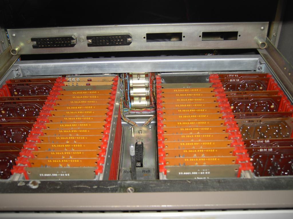
Thanks to Mr. Klittich from Frankfurt/Main who donated some remains of an RA 770 analog computer he was working with during the 1970s and 1980s I had some spare function generator cards in stock, so I could populate the NNT 771 drawer which can be seen on the left (please note that only half of the slots are occupied - this does not mean that there still is space left - the function cards I used need two slots each, so the NNT 771 like shown above is on its maximum). The picture on the top right shows such a pair of function generator cards. This pair, called SIN 1A and SIN 1B, implements the function sin(pi/2 * x) for x varying between +/- 1 machine unit (10 V). | |||||||||||||
|
On the right the front plate of the next expansion drawer, the quad variable function generator VFG 801, can be seen. It contains four diode function generators. |

|
||||||||||||
|
The top view of the VFG 801 can be seen on the left. On the bottom the 21 potentiometers of one of the four function generators can be seen. The card cages above this section hold the precision voltage dividers, the diodes and the necessary operational amplifiers (two per function generator making a total of eight amplifiers per drawer). |
||||||||||||
|
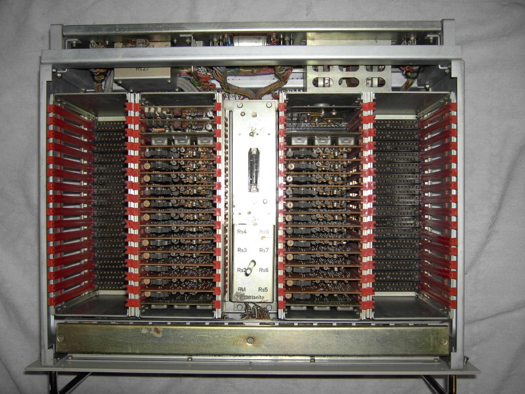
Located behind the analog patch field is the central computing element magazine holding up to 60 high precision, chopper stabilized operational amplifiers and their associated computing networks containing high precision resistors and capacitors as well as lots of control relays. The picture on the right shows the empty magazine. |
|
||||||||||||
|
|
||||||||||||
|
Located under analog patch field are two blocks holding the high precision integrator capacitors for 60 integrators in two drawers, one of which is shown above. |
|||||||||||||

|

|
||||||||||||
|
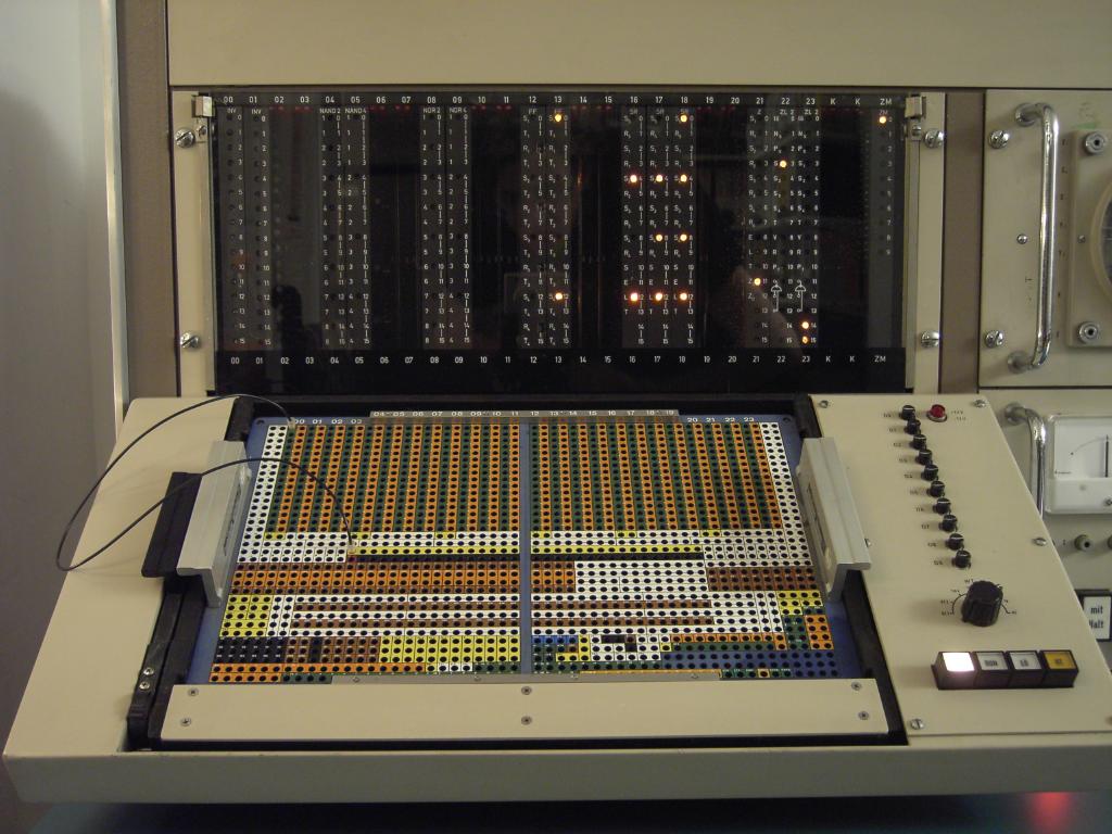
The two pictures above show the central shielded analog patch field of the RA 770 analog computer. The patch panel is easily removable thus allowing rapid change of programs on the machine. In contrast to other machines made by EAI, Dornier etc. the RA 770 uses coaxial connectors throughout the patch field instead of cheap finger contacts being pressed to spring contacts. The quality of this Telefunken development is so high that the patch panel still has not a single weak contact after all this time and the storage conditions the machine has experienced. This is in sharp contrast to most EAI systems known to me which need regularly careful cleaning of the patch field and its contacts. Located under the patch field are sixteen hand set coefficient potentiometers and eight hand set switches. A very special feature of these potentiometers is the fact that four of them can be coupled together by turning a knob thus forming two precision double potentiometers. This is a unique and very useful feature I have never seen on any other analog computer and makes the rapid setup of manually controlled sweep generators and the like easy. |
|||||||||||||
|
|
||||||||||||
|
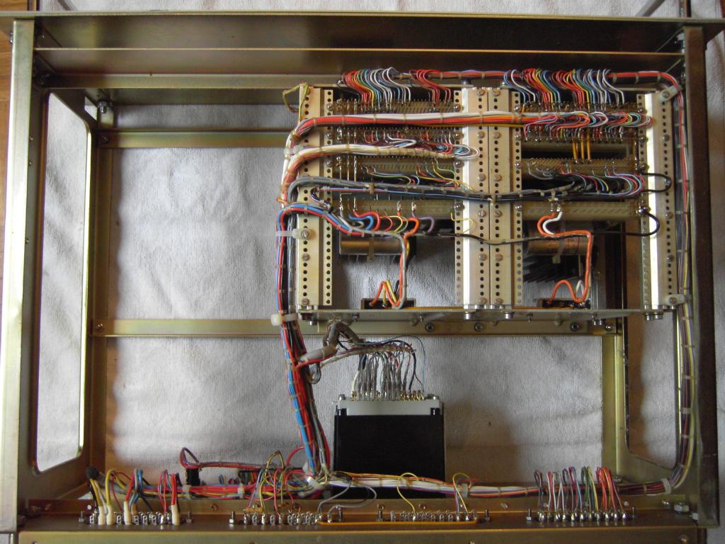
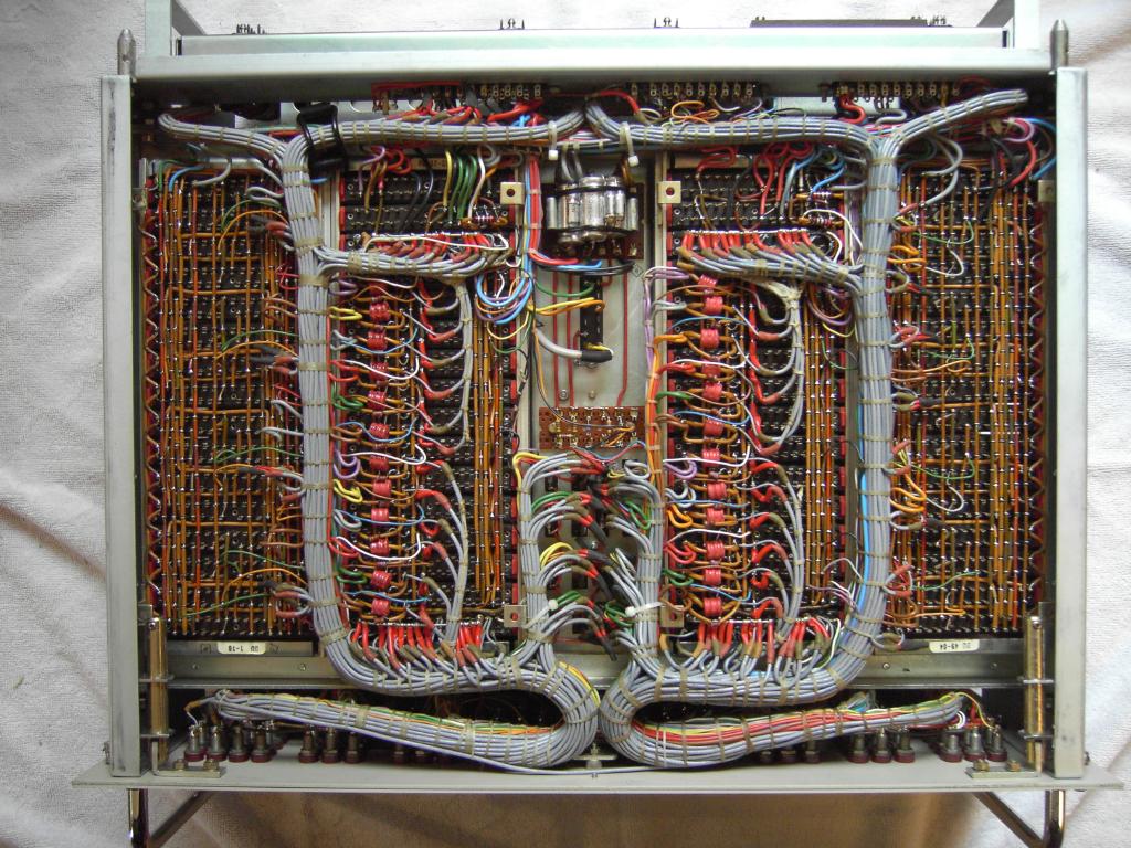
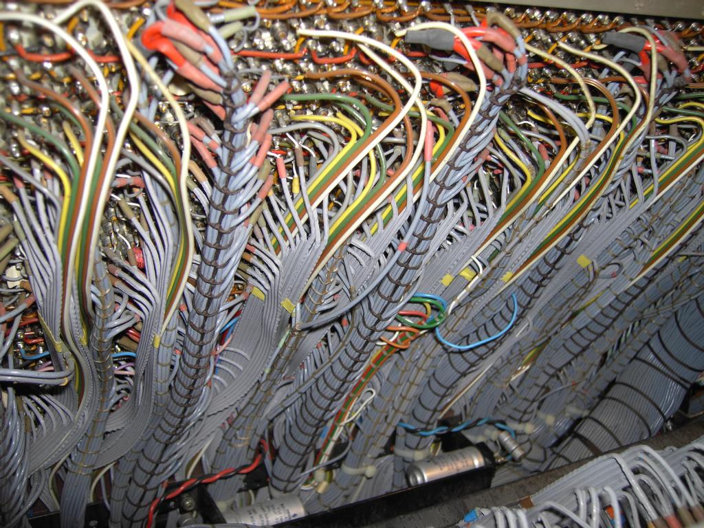
The two pictures above show the cabling behind the analog patch field connecting it with the central computing element magazine and the various other components of the RA 770. |
|||||||||||||
|
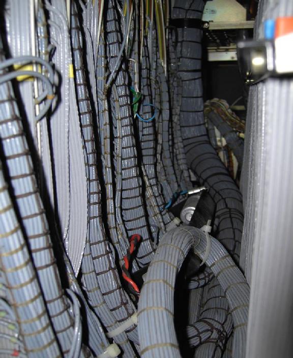
On the left the cabling behind the central computing element magazine which is located behind the analog patch field can be seen. |
||||||||||||
|
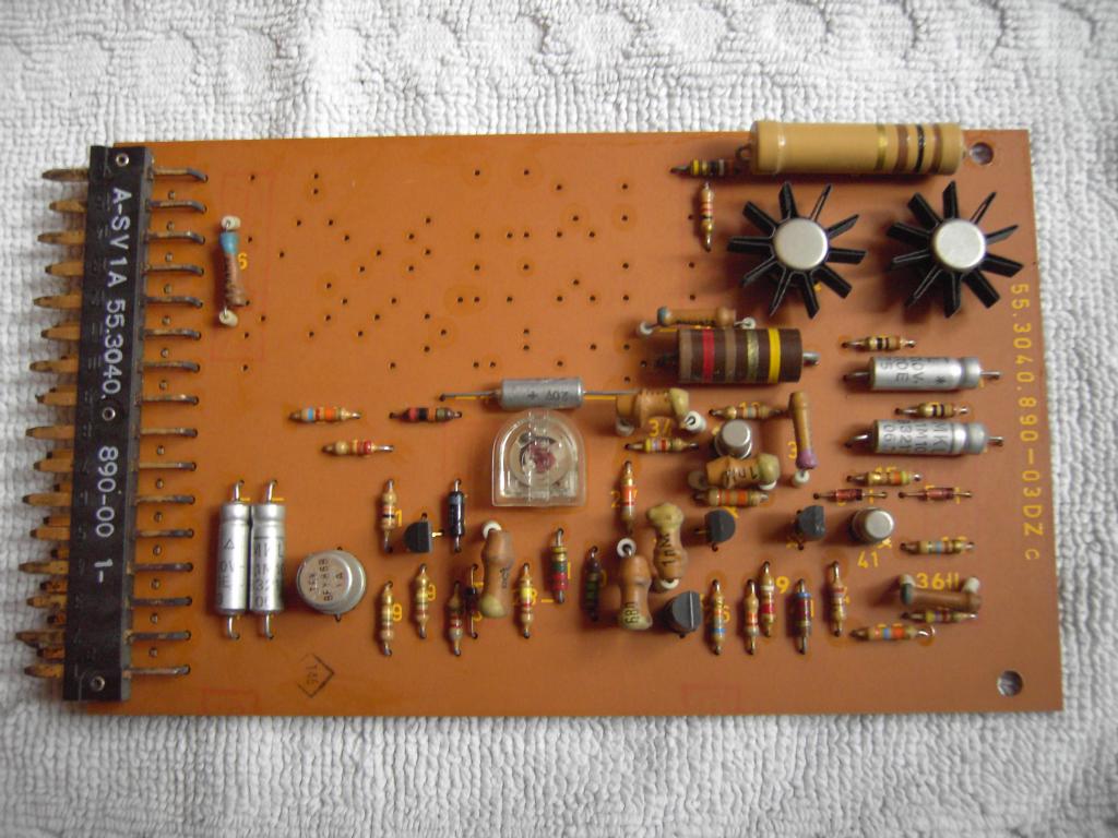
The RA 770 uses chopper stabilized amplifiers in every place where extreme high precision and low drift is of prime importance (integrators, etc.). Some places with lower overall precision like function generators and the like allow the use of simpler operational amplifiers. One of these amplifiers is shown on the right - this board is called SV 1A and contains a single amplifier without chopper stabilization and without overload detection. This type of amplifier is, for example, used in the NNT 771 drawer. |
|
||||||||||||
|
The picture on the left shows one of the best operational amplifiers ever made for an analog computer. This is the so called OP14 from Telefunken (designed by Prof. Dr. Meyer-Brötz who developed the first transistorized operational amplifiers for Telefunken - even before companies like EAI did). On the right, under the metal shield, the semiconductor chopper and demodulator circuits are located. Below this shield the two power output transistors can be seen. The left half of the card contains the discretely implemented input stages of the main amplifier. The since integrated circuit is an off the shelf operational amplifier which is used for the chopper driven drift cancellation. This is the place where the overload detection takes place, too. |
||||||||||||
|
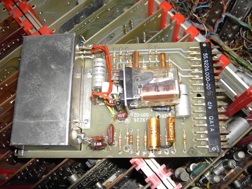
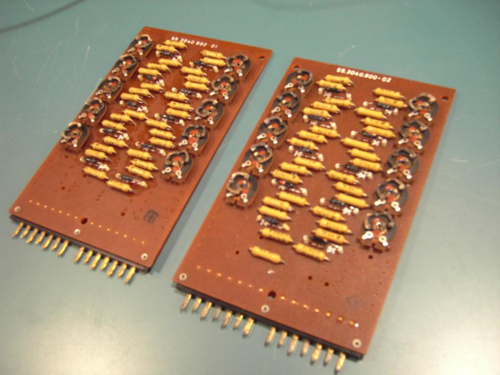
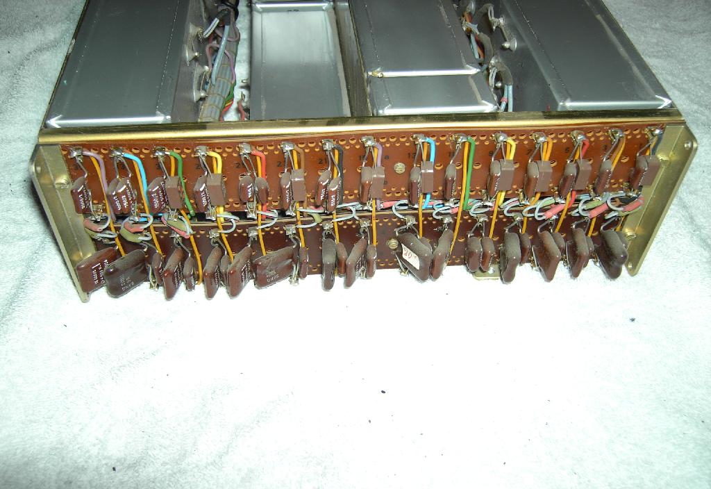
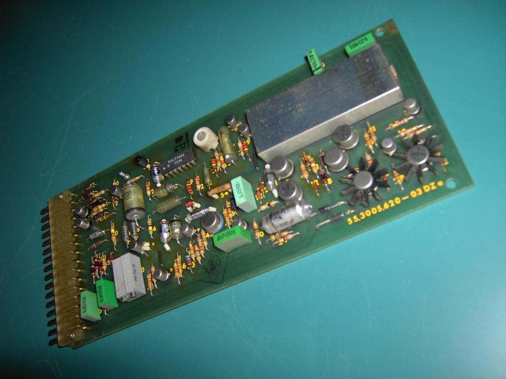
On the right, a SK22 board is shown. This board contains the high precision resistors and control relays to implement two summers in the RA 770. |
|
||||||||||||

|
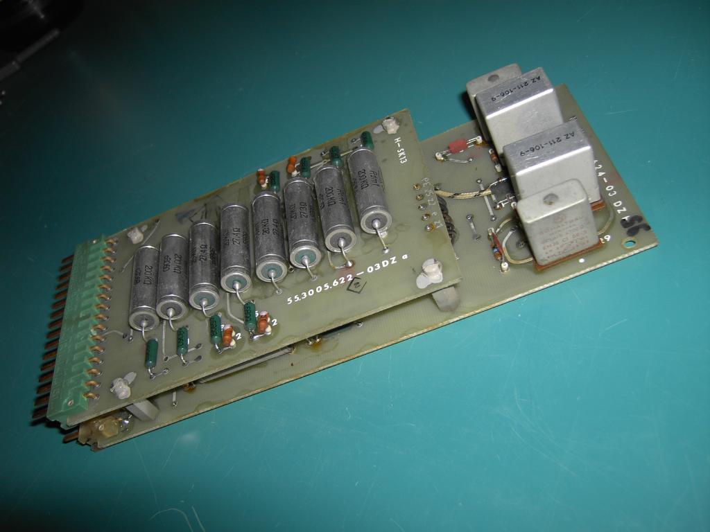
Its more complex counterpart, the SK41, can be seen on the left. This board contains the control logic, precision resistors and capacitors to form two multi function integrators/summers in conjunction with two OP14 operational amplifier cards. The extreme number of relays used on this board is due to the fact that all integrators in the RA 770 feature a dynamic test mode which adds quite complexity. The integrator control is, of course, purely electronic and does not involve slow relays. |
||||||||||||
|
Documentation:The documentation for this great machine is just overwhelming - its quality and quantity are really outstanding. Up to now only a few bits of documentation have been scanned and are available here:
Conclusion:This completes this short page about the truly wonderful Telefunken RA 770 analog computer. I will in the future post more information about the system when I have gained more experience and have completed some more difficult computations on the system as by now.
01-DEC-2007, ulmann@analogmuseum.org |
|||||||||||||