|
Some computations involving analog computers require a random noise source - think, for example, of a system consisting of several masses which are coupled to each other using springs and dampers (like a car suspension system). Such a system may be excited by a random noise source, thus simulating a bumpy road. Other uses involve the study of filter simulation or stochastic processes. There are many applications requiring a good random noise source. Since real time simulations of mechanical systems require quite low frequency random signals as excitation values, it is rather difficult to build a random signal generator for this purpose. Professional devices will amplify the Nyquist noise of a resistor, mix it with a fixed frequency (normally about 300 kHz) to create an IF down to 0 Hz and amplifiy and filter this. When you have a look at the drawings of a professional random noise like the Wandel und Goltermann RG-1, it becomes clear that building a good random noise source is a major project which will not be completed in a weekend. Fortunately, I have a Wandel und Goltermann RG-1 noise generator which seemed ideally suited as a random source for my analog computers. The problem to be overcome is the frequency range of the device. Normally it delivers white noise between 0 Hz and 100 kHz (there are some filters like a speech filter, but these filters are not satisfactory for my plans), but I need something like noise between 0 Hz and
So it was clear that I had to build a high order low pass filter to be switched between the analog computer and the random noise source. I decided to employ a switched capacitor filter to facilitate the overall design - after having a look at modern integrated circuits I decided to use the MAXIM MAX293 - an elliptic low pass filter of eighth order which requires a TTL clock signal of 100 times the cutoff frequency. |
|
|
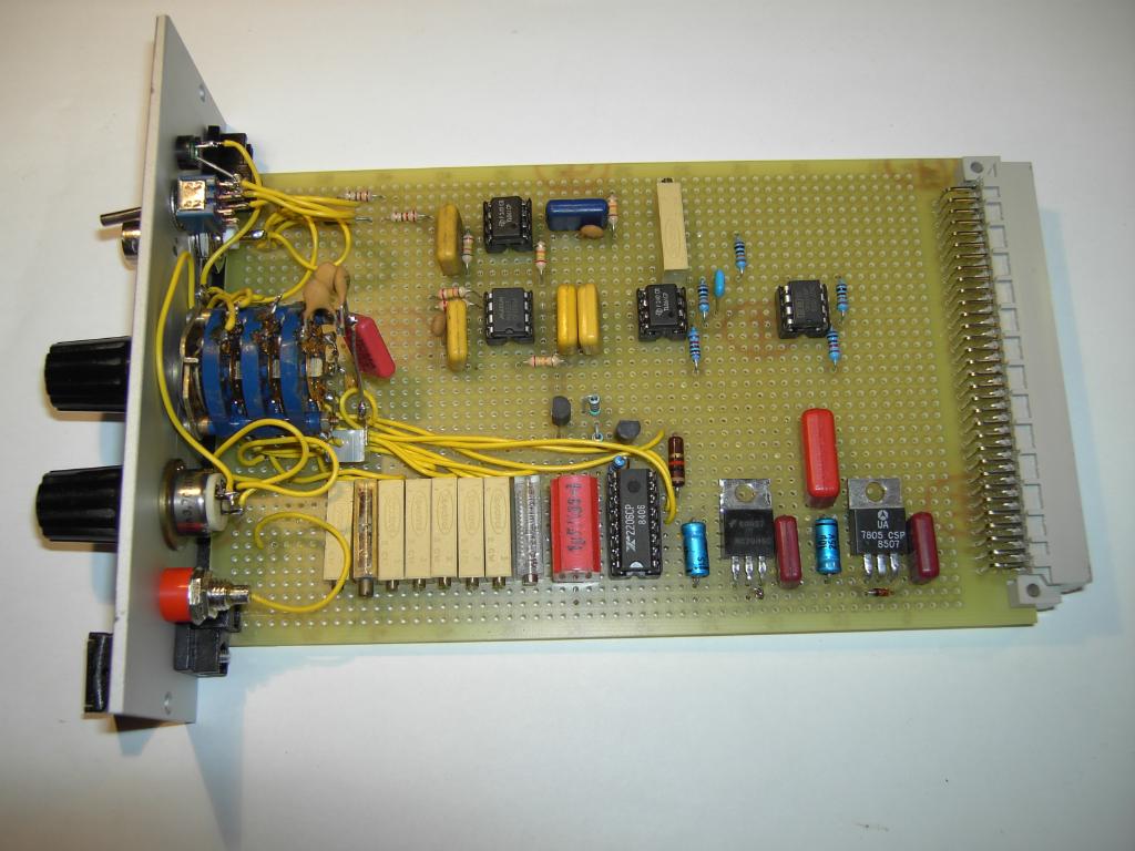
The picture on the left shows the overall circuitry of the completed
low pass filter. It consists of the following part:
|
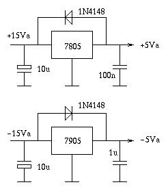
| Let us start with the power supply which is rather simple since the 19 inch frame the card mounts in already has a power supply delivering +/-15 V, +5 V (for digital circuitry) and +/-10 V. Since the switched capacitor filter requires a +/-5 V supply, I derive these voltages from the +/-15 V supply using to constant voltage regulator ICs. |
|
|
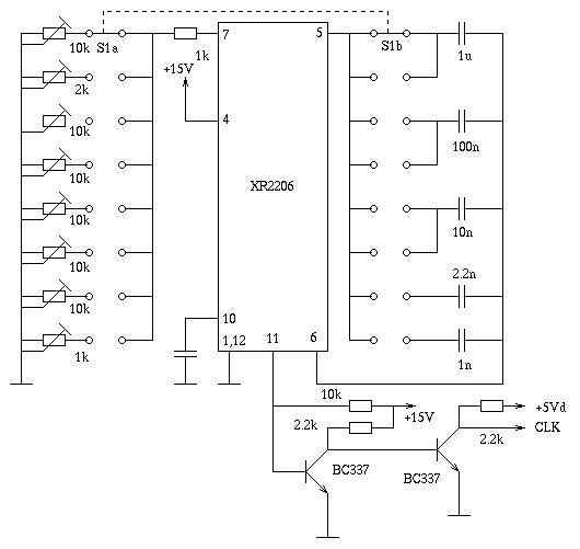
The clock generator is a bit more tricky - since the filter has eight different switch selectable bandwidths, the clock generator must be capable of delivering eight preset frequencies. I decided to use the rather well known XR2206 function generator IC since it is easy to use and does its best to generator a 1:1 duty cycle. The clock generator is shown in the following picture:
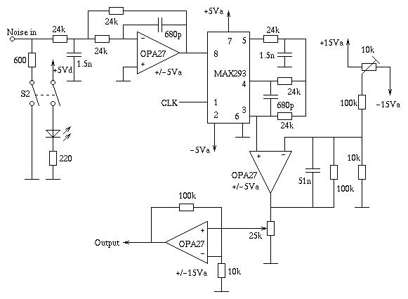
The filter is shown in the next picture. The input signal from the RG-1 can be terminated with a 600 Ohm resistor. After this it is fed into a discrete low pass filter with a cutoff frequency of 5 kHz before being used as input for the MAX293. This IC does not only contain the switched capacitor filter but also a dedicated operational amplifier which is used to implement another discrete filter with a cutoff frequency of 5 kHz. The output of the MAX293 is then fed into a non-inverting amplifier with an amplification rate of about 10 (11 to be exact :-) ). This is the place where the drift compensation occurs - the switched capacitor filter introduced quite a lot of drift. The output of this operational amplifier is then used as the input signal for a voltage divider before being amplified another time by a factor of 10 (11).
|
|
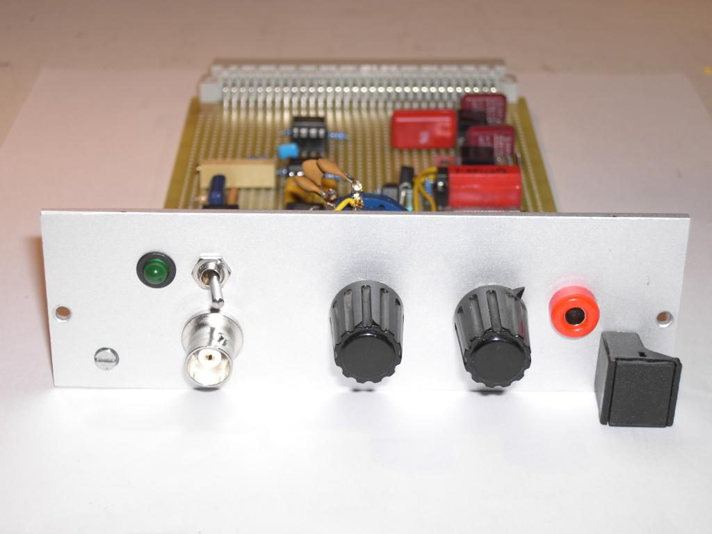
The picture on the right shows the front of the random noise filter.
From left to right the following elements can be seen:
|
|
|
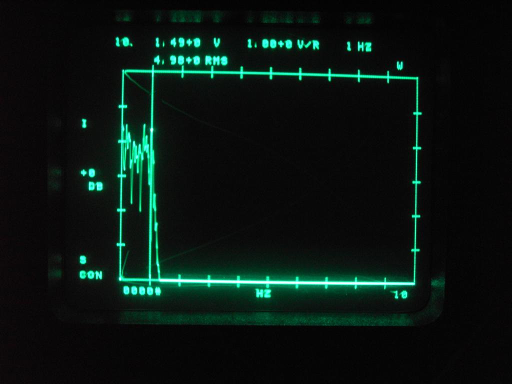
The picture on the left shows the output frequency spectrum of the filter being fed with a 100 kHz random noise signal from the RG-1. The filter has been set to a cut off frequency of 1 Hz only (which is what I need for my moving mass excitation computation) - it is incredible how sharp the cutoff point in fact is (and it shows how good the RG-1 is - even at very low frequencies is is a good white noise signal) - the vertical hairline has been set at 1 Hz. |