The EAI 680
|
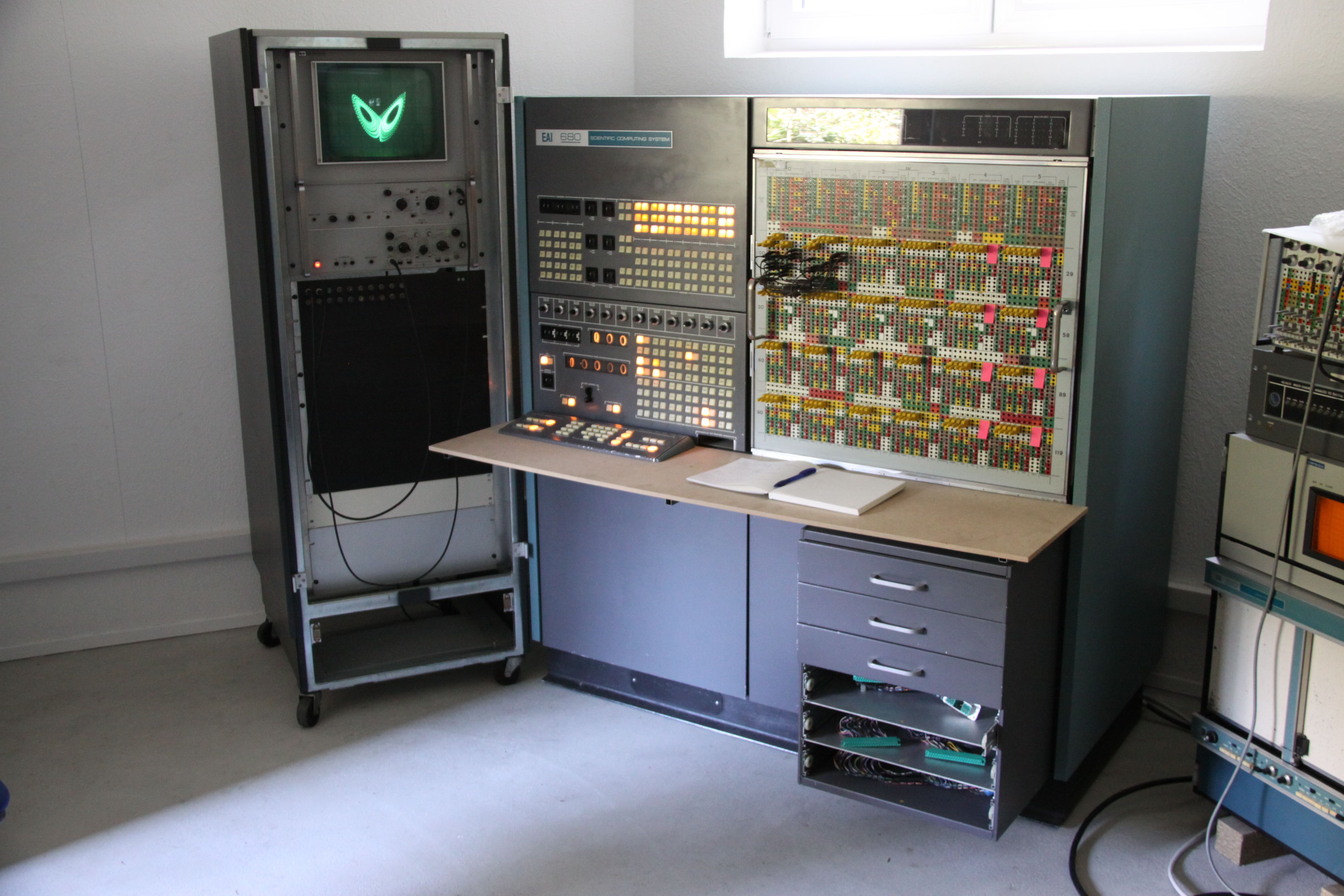
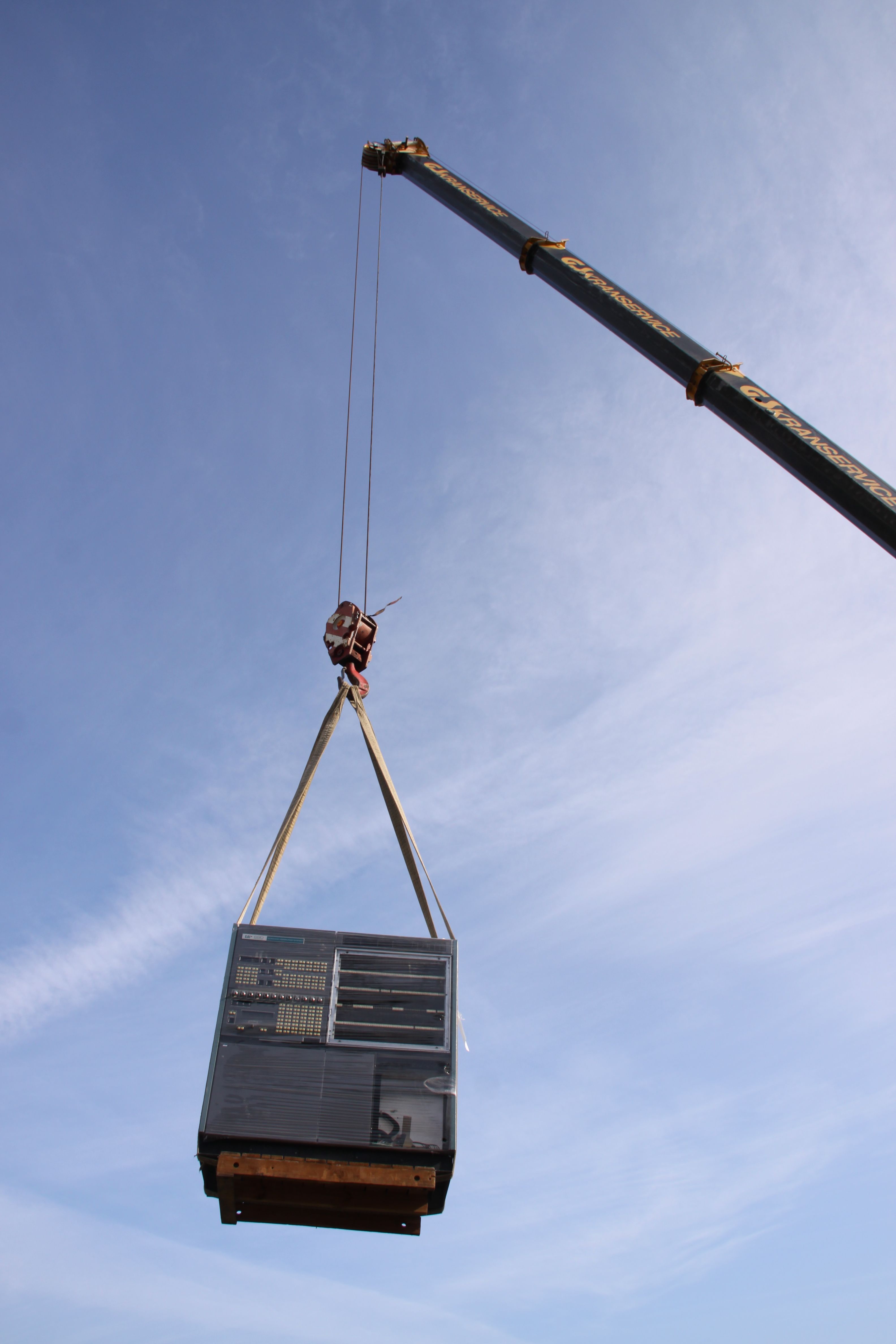
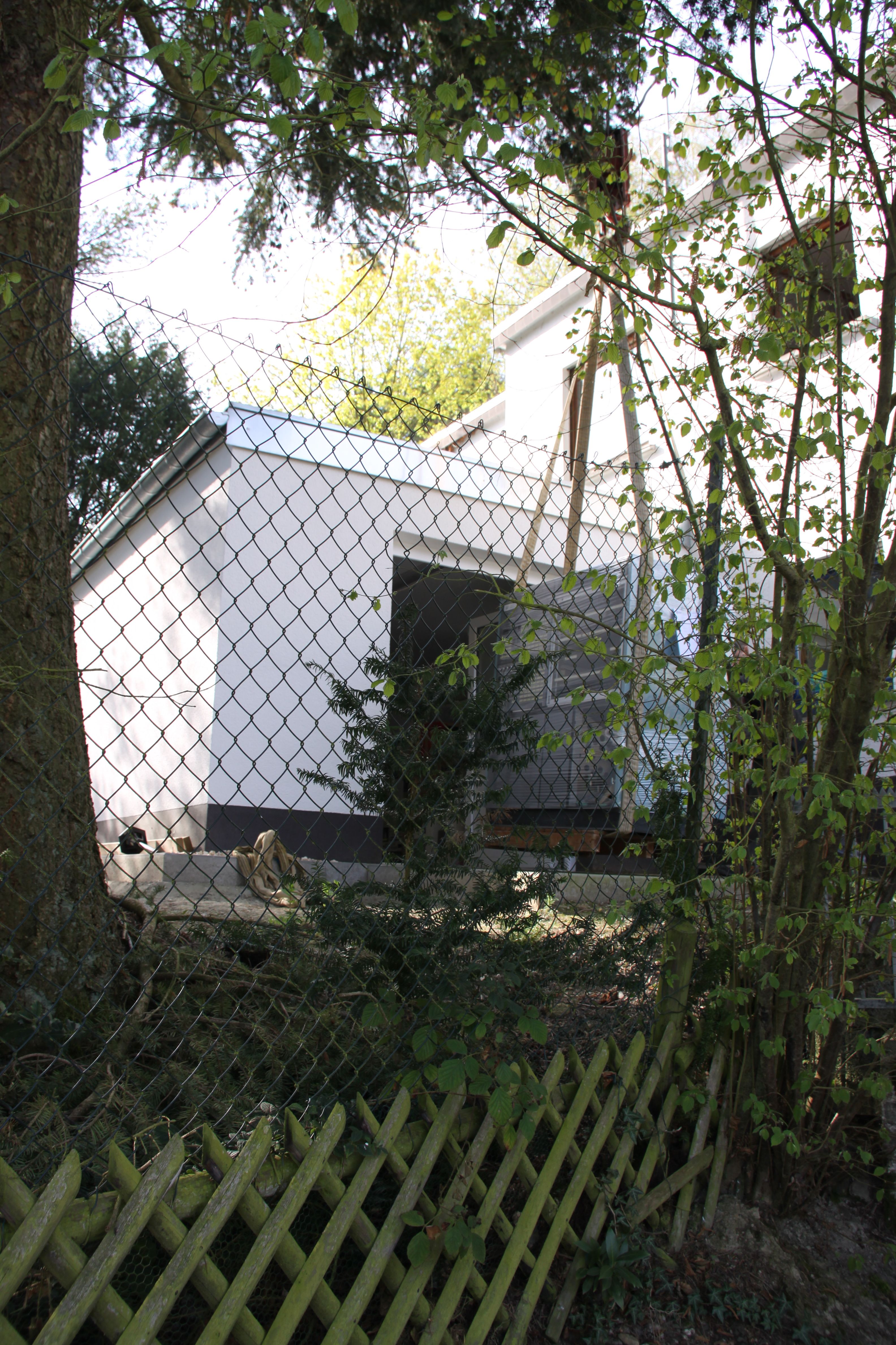
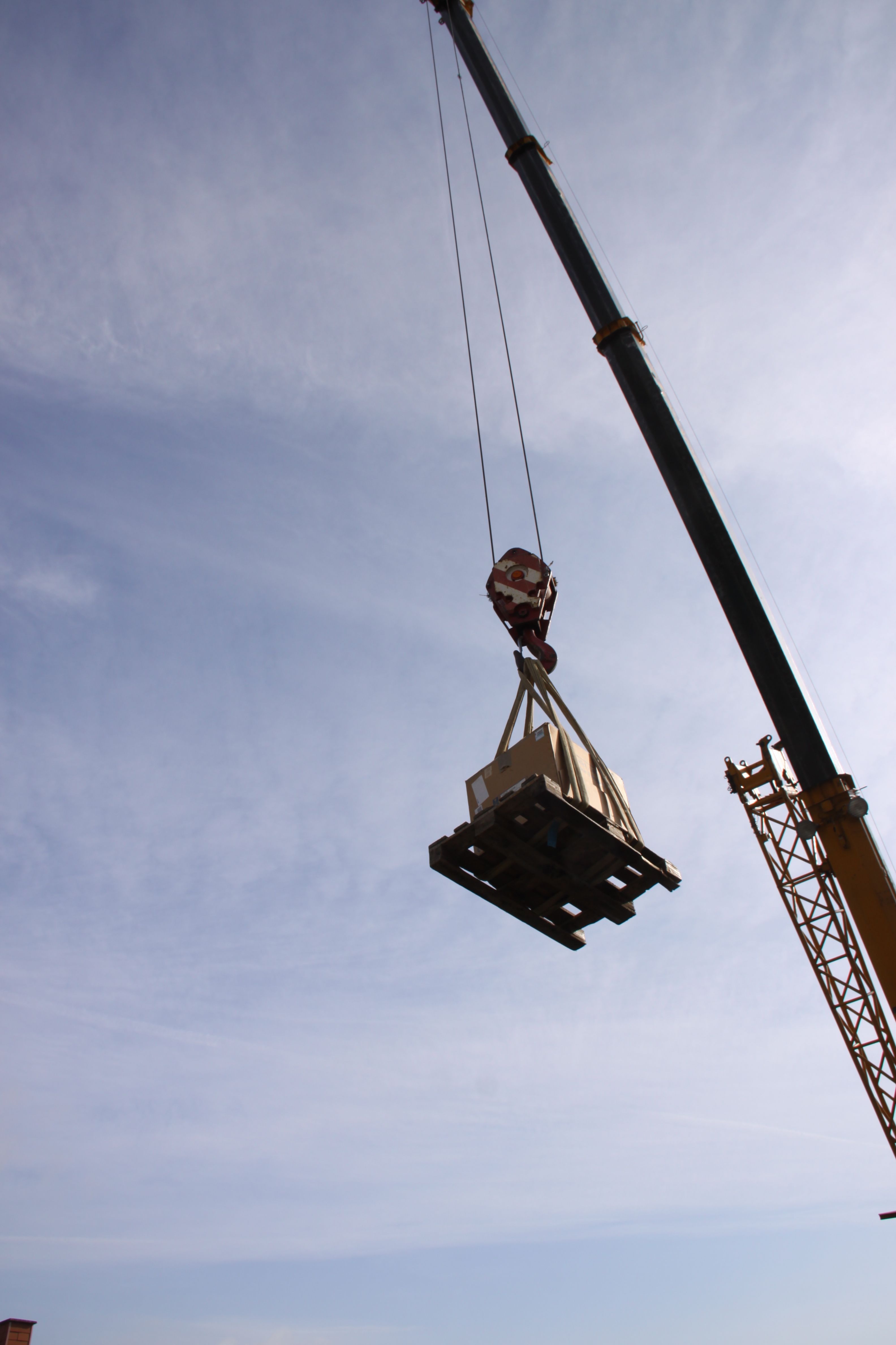
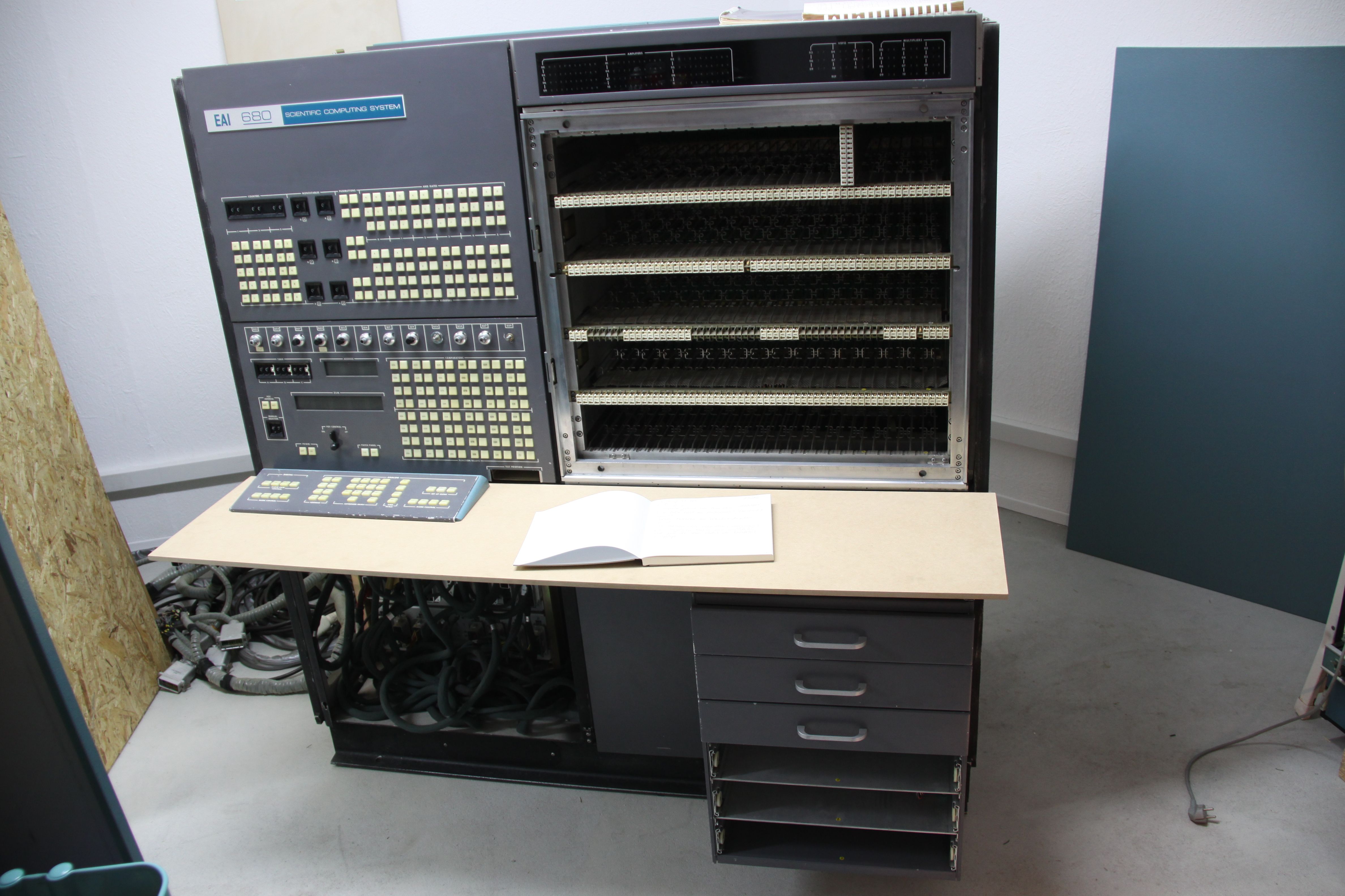
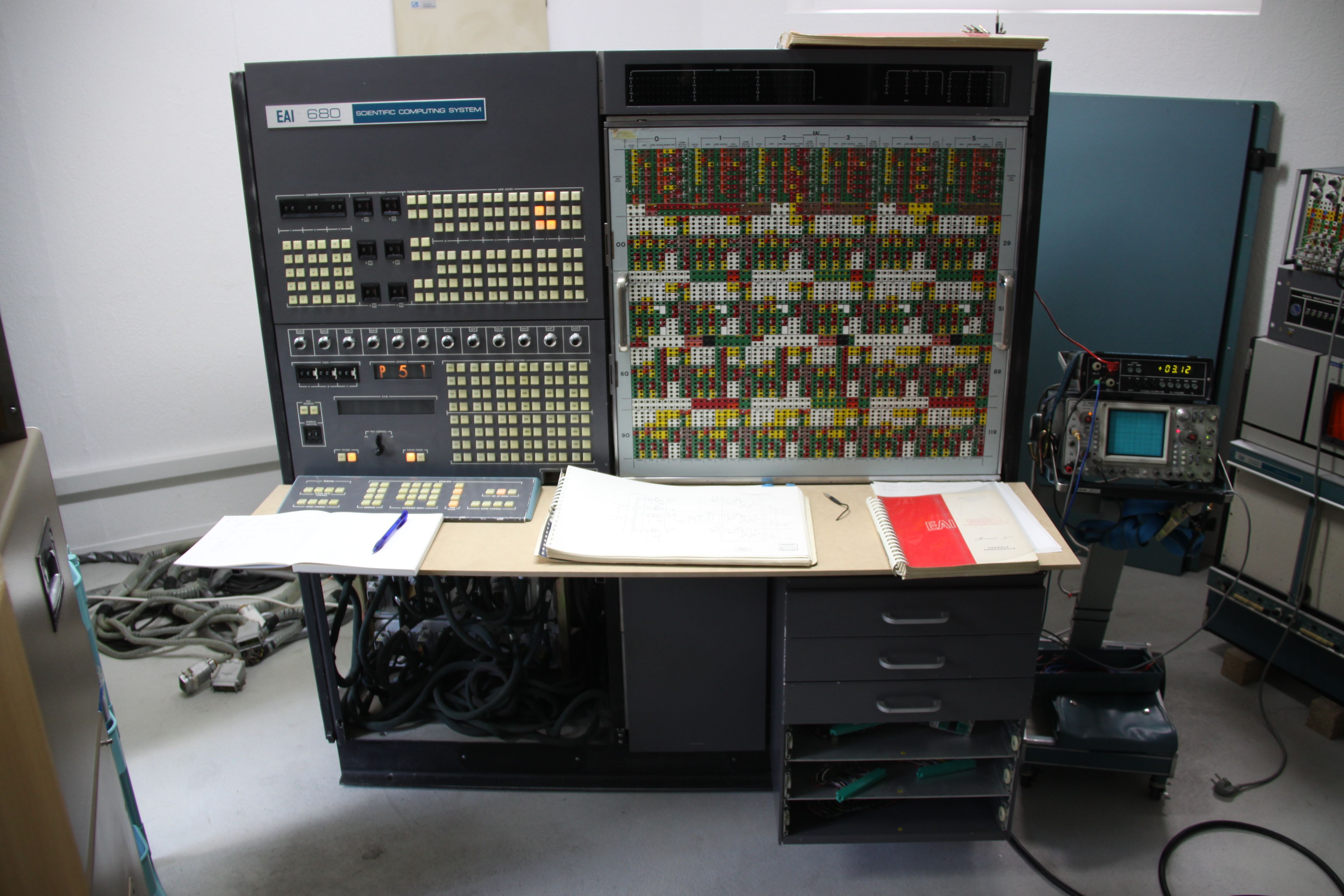
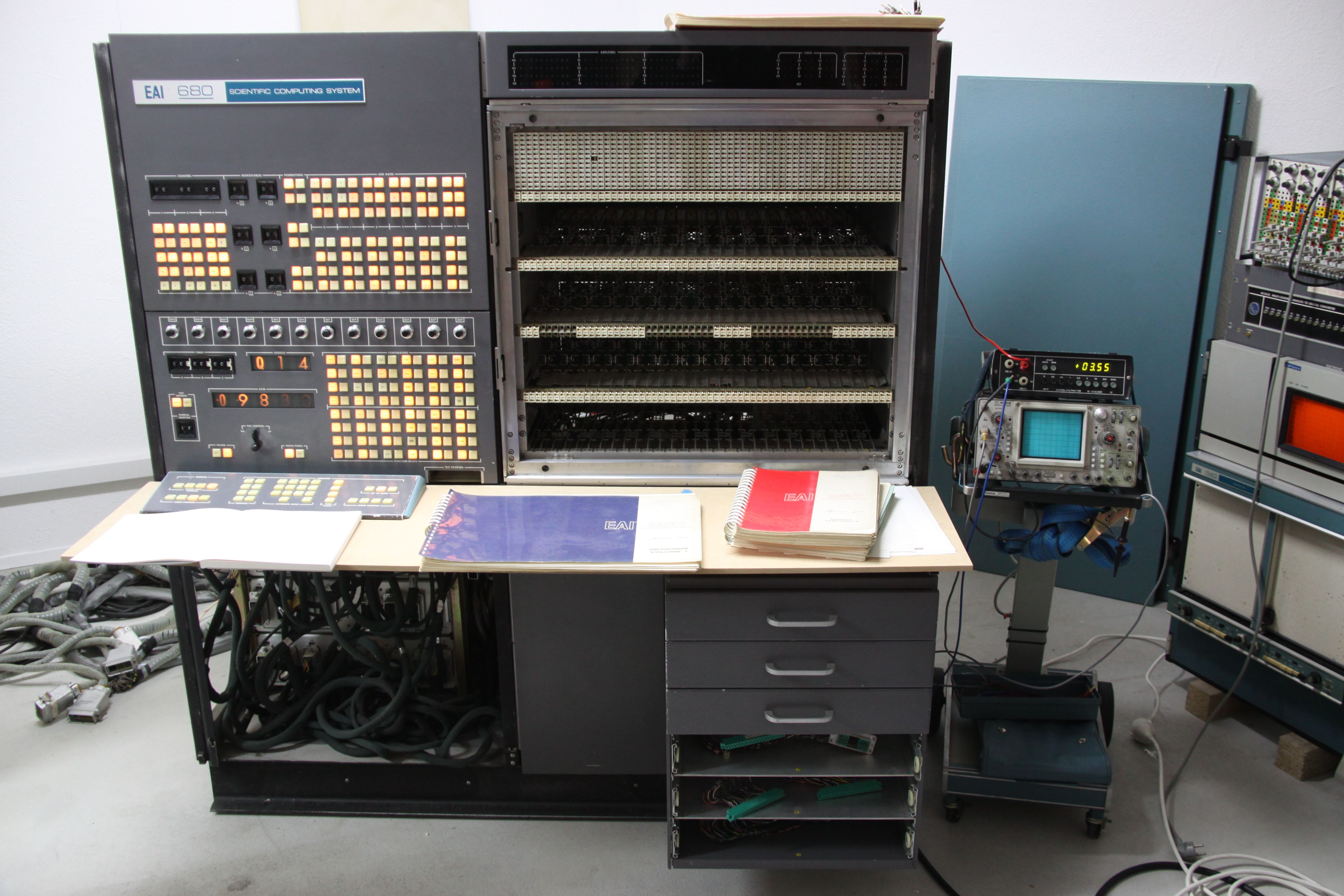
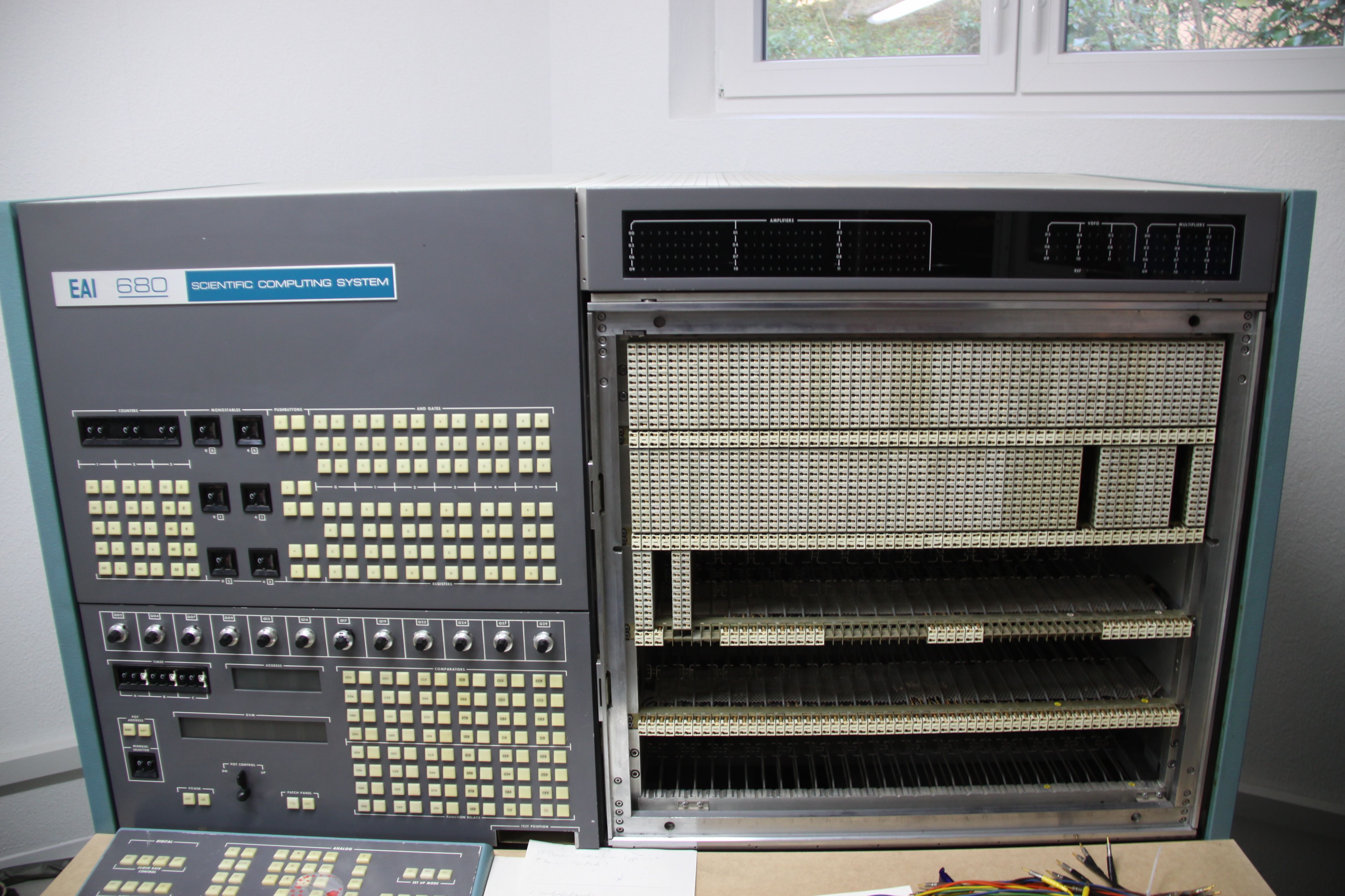
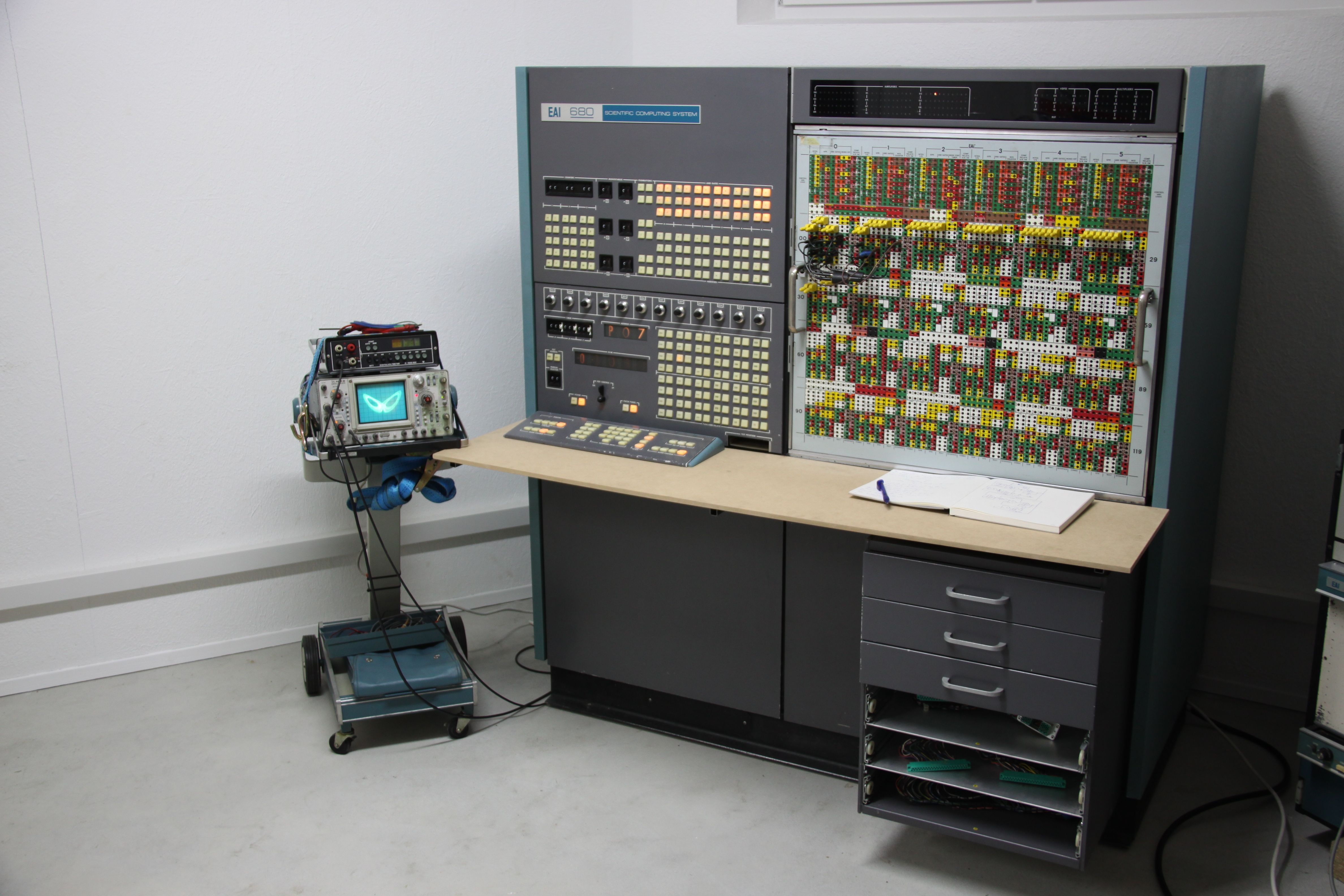
About three years ago, in 2011, we got an EAI 680 analog computer which was donated to us by another museum. As this machine was too heavy and large to fit into the existing location, it was stored at a shipping company. In the meantime we (my beloved wife Rikka and I) built an annex to the house which was triggered by our acquisition of an even larger EAI Pacer 700 (which is a story by itself). In April 2014 both machines, the EAI Pacer 700 and the EAI 680 described here, finally found their new home in this annex. This page gives an impression of this analog computer and the restauration process. The picture above was taken in late April 2014 after about 50 hours of restauration and repair work and shows the machine, which is mostly operational already, together with a large-screen oscilloscope displaying a Lorenz attractor. Since the annex built for the two large EAI machines can only be accessed through stairs, the EAI 680 (and the Pacer 700 as well) had to be lifted by crane over the garage, some (small) trees etc. as shown below. From left to right the pictures show the EAI 680 without her analog modules on the crane's hook, its final landing point in front of the annex, and a large box containing the 142 analog computing modules. The empty machine weighs about 750 kg while the modules weigh about 250 kg.
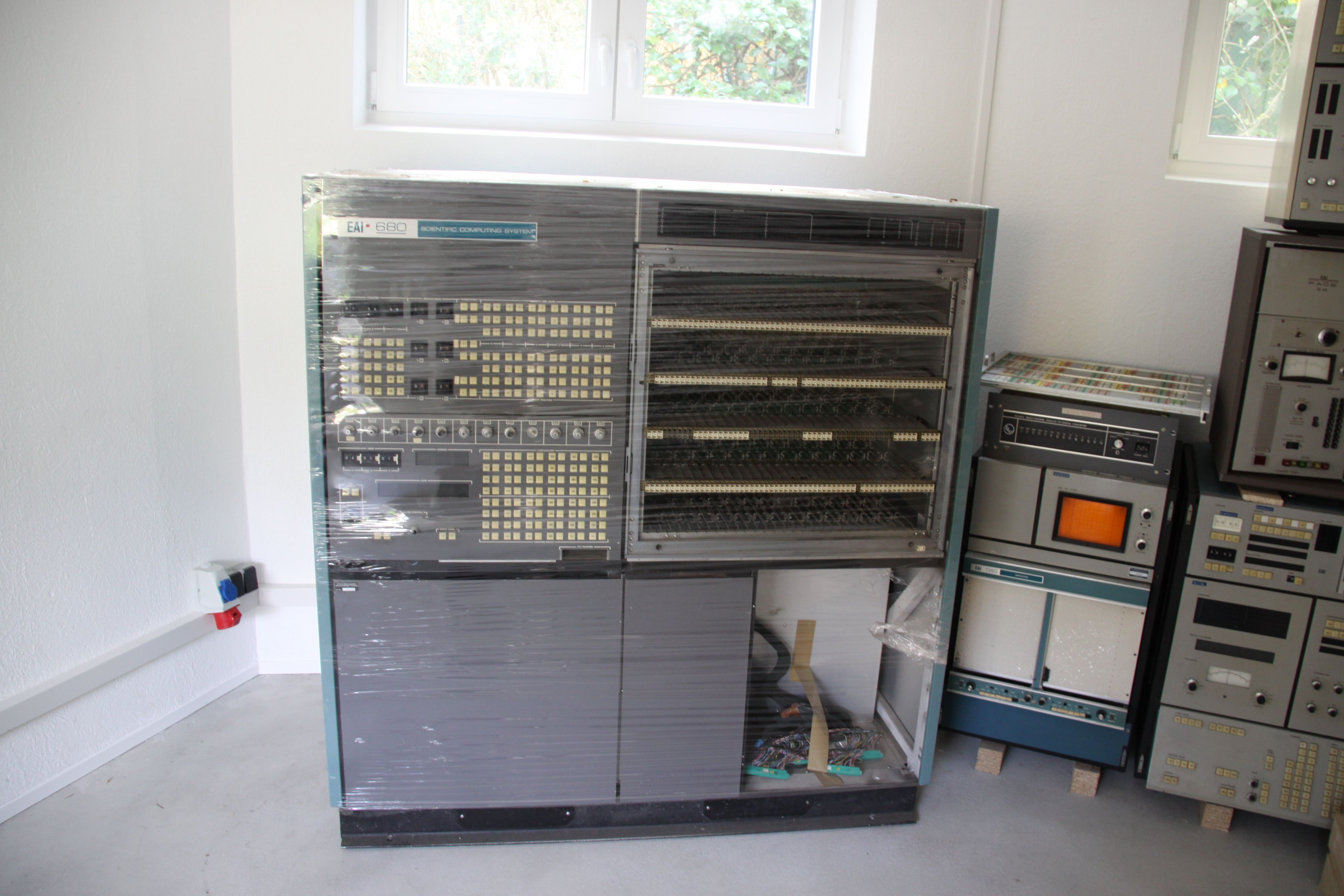
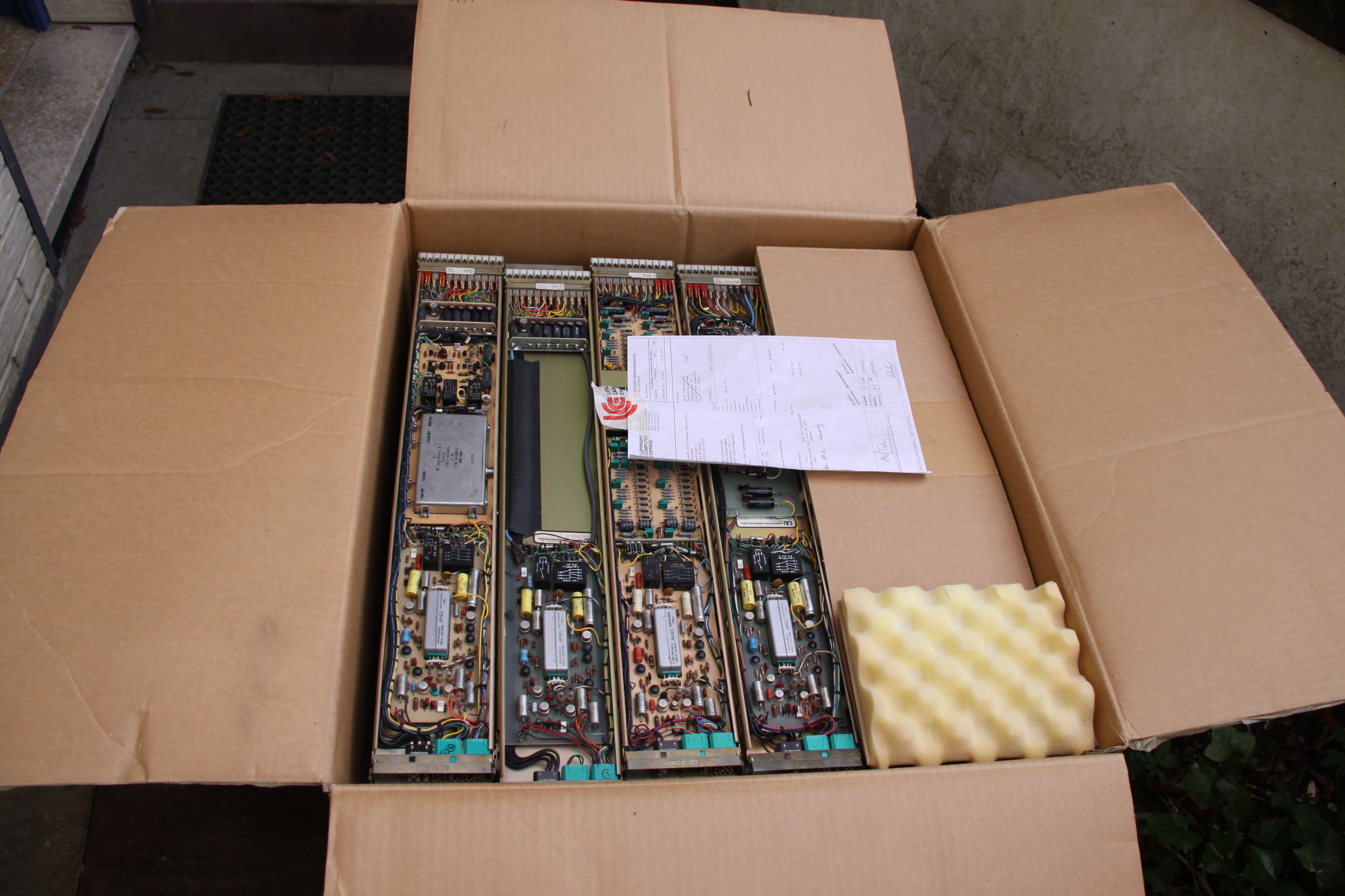
The following pictures show the still shrink-wrapped EAI 680 at its new location just left to an EAI 580 with its oscilloscope and plotter, and the box with the many analog computing modules. |
|
|
|
|
|
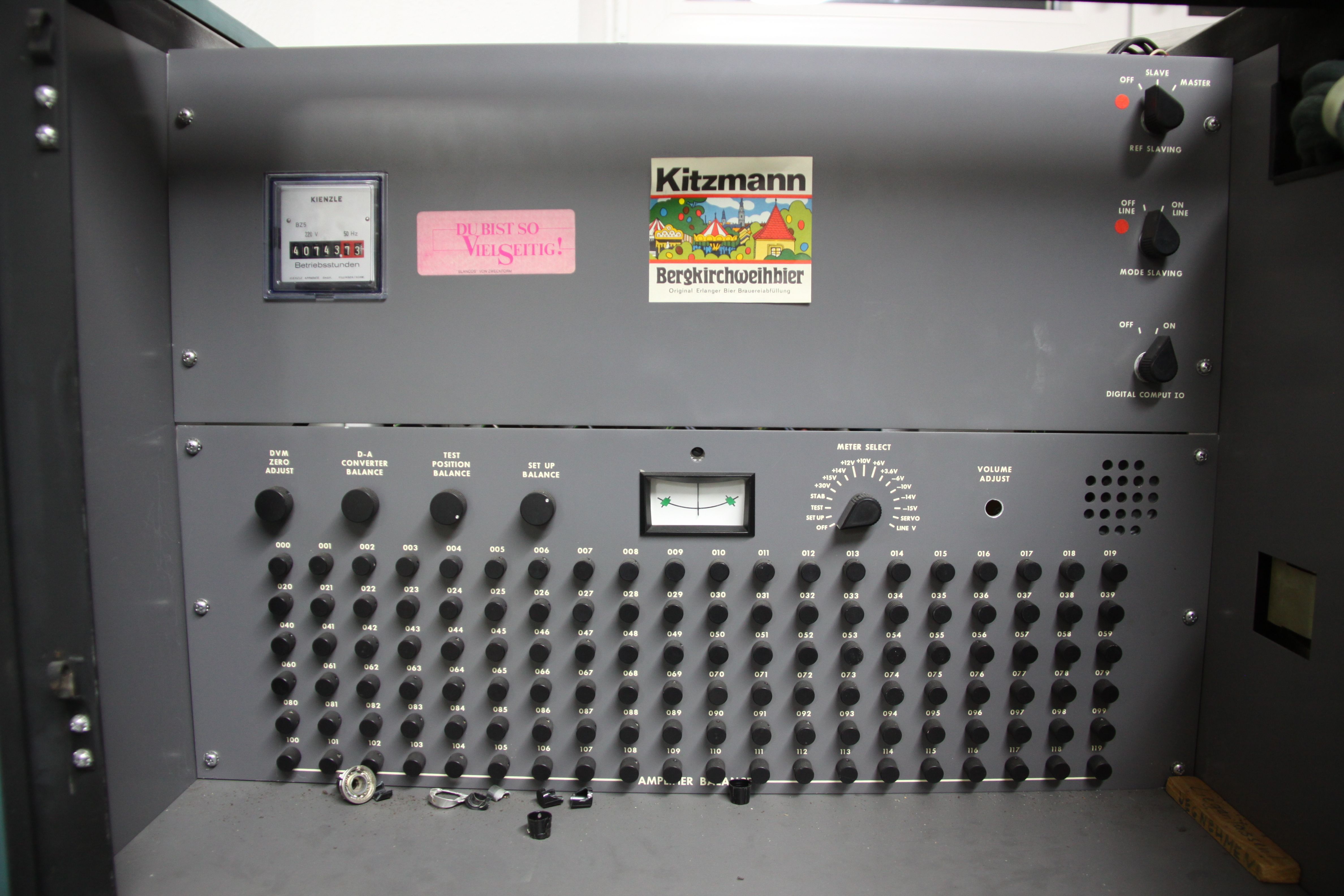
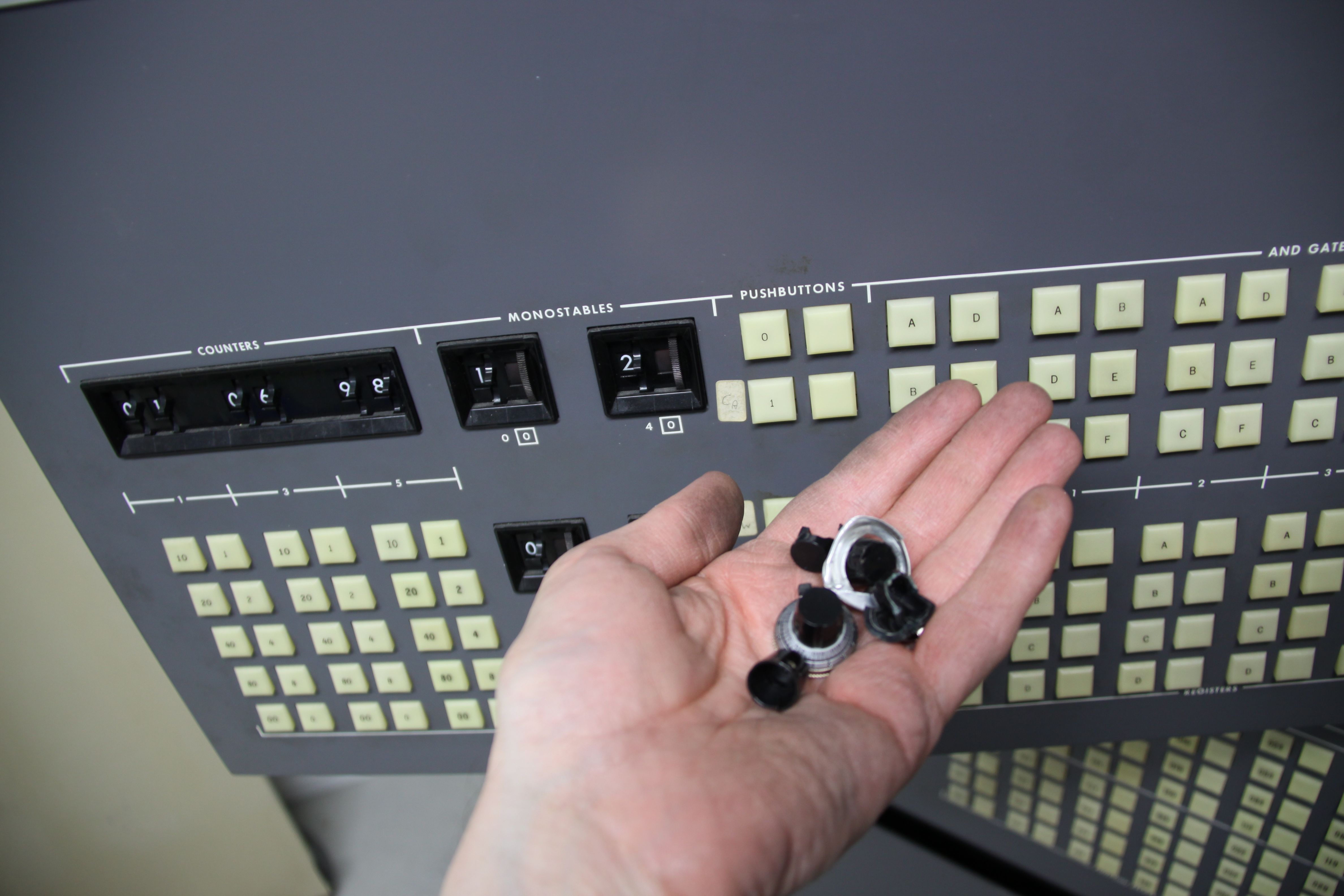
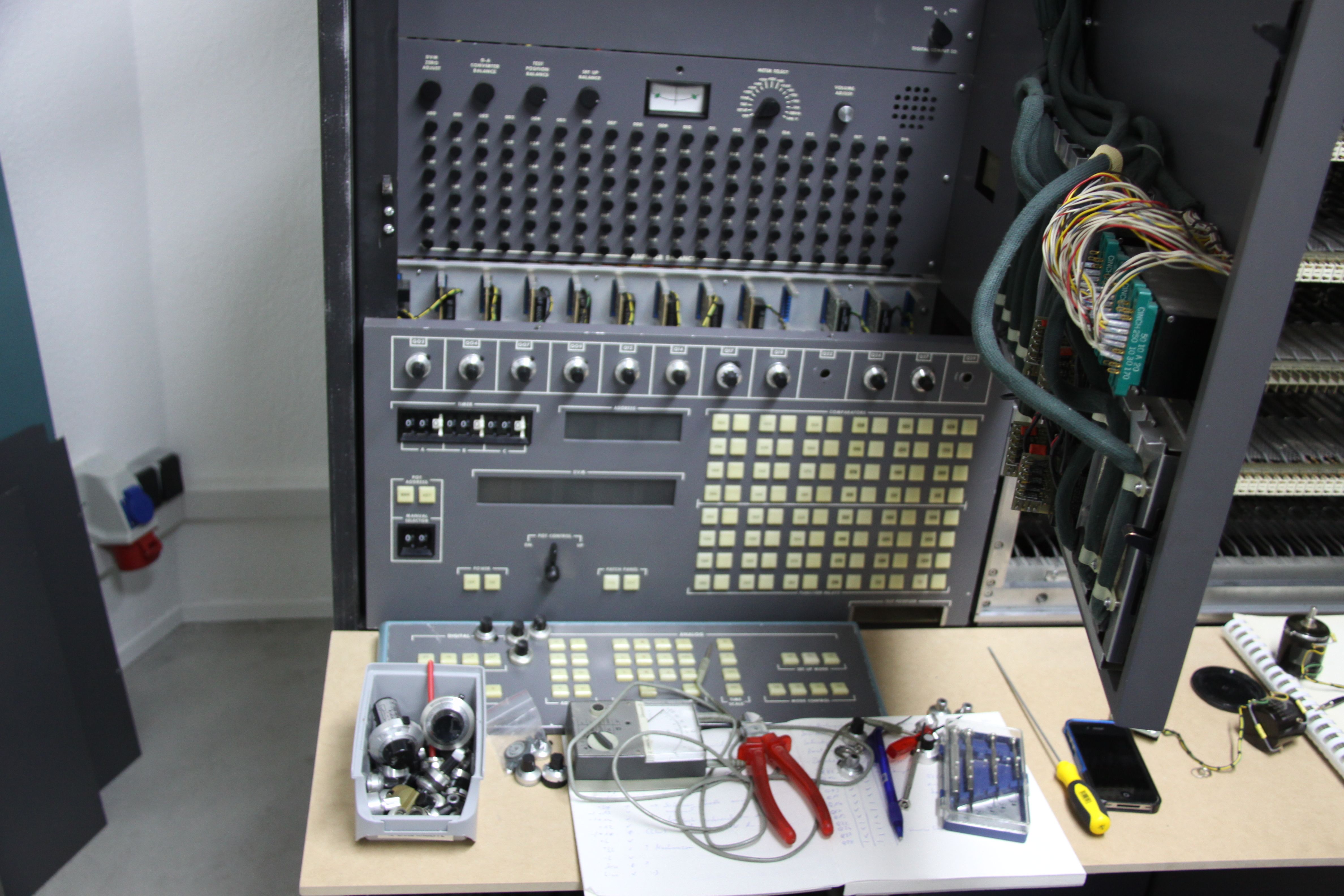
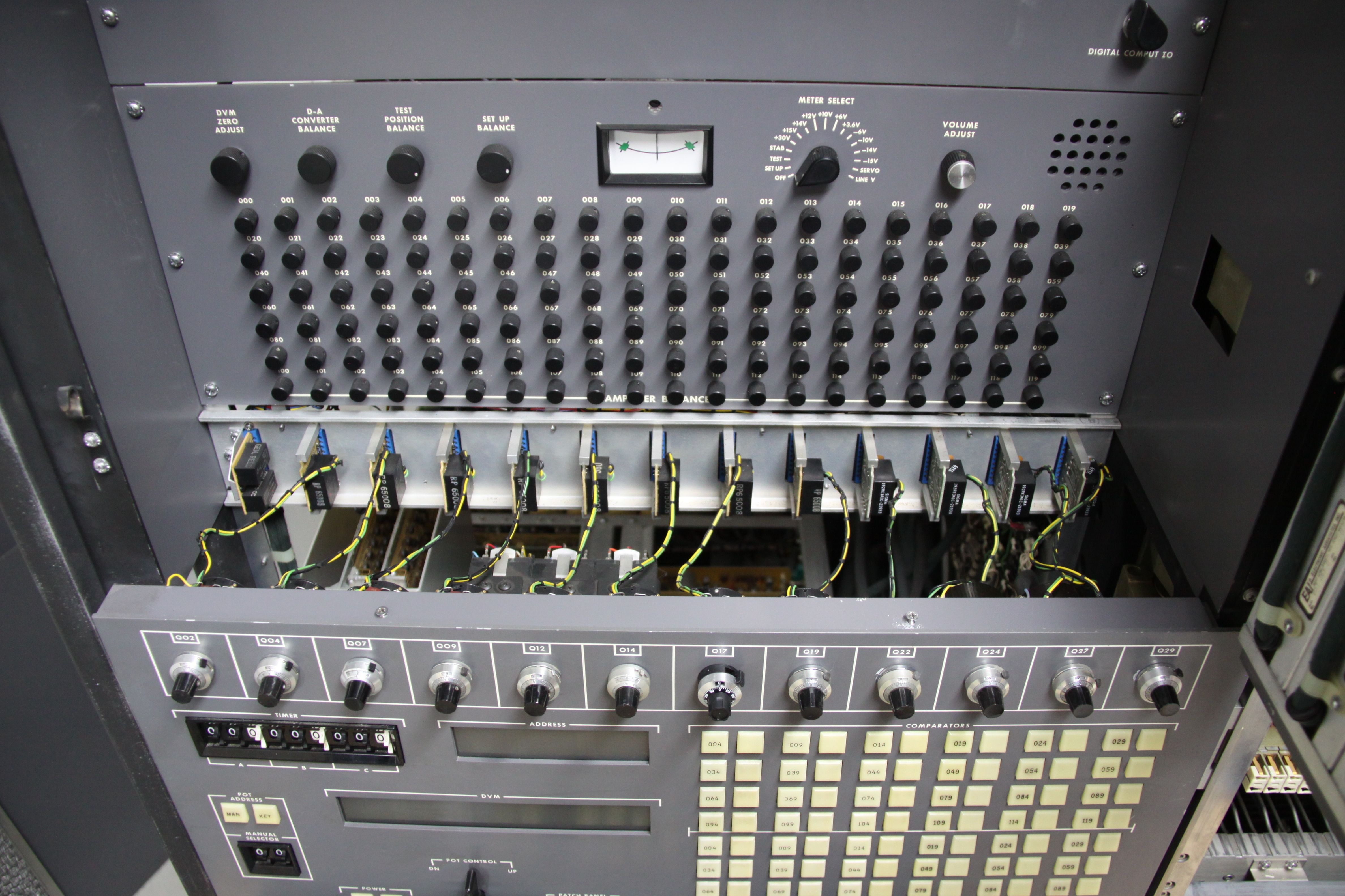
Prior to repairing a machine like this, a thorough inventory has to be taken concerning it current status, obvious damage, missing parts, etc. The following pictures were taken during this phase. The picture on the left shows the area behind the control panel containing the many potentiometers to balance the amplifiers as well as some junk from long ago (the machine was built in 1967 and ran, according to the counter in the upper left, for 40743 hours!). In the picture on the right I hold some severely damaged precision knobs from the ten-turn potentiometers. |
|
|
|
|
|
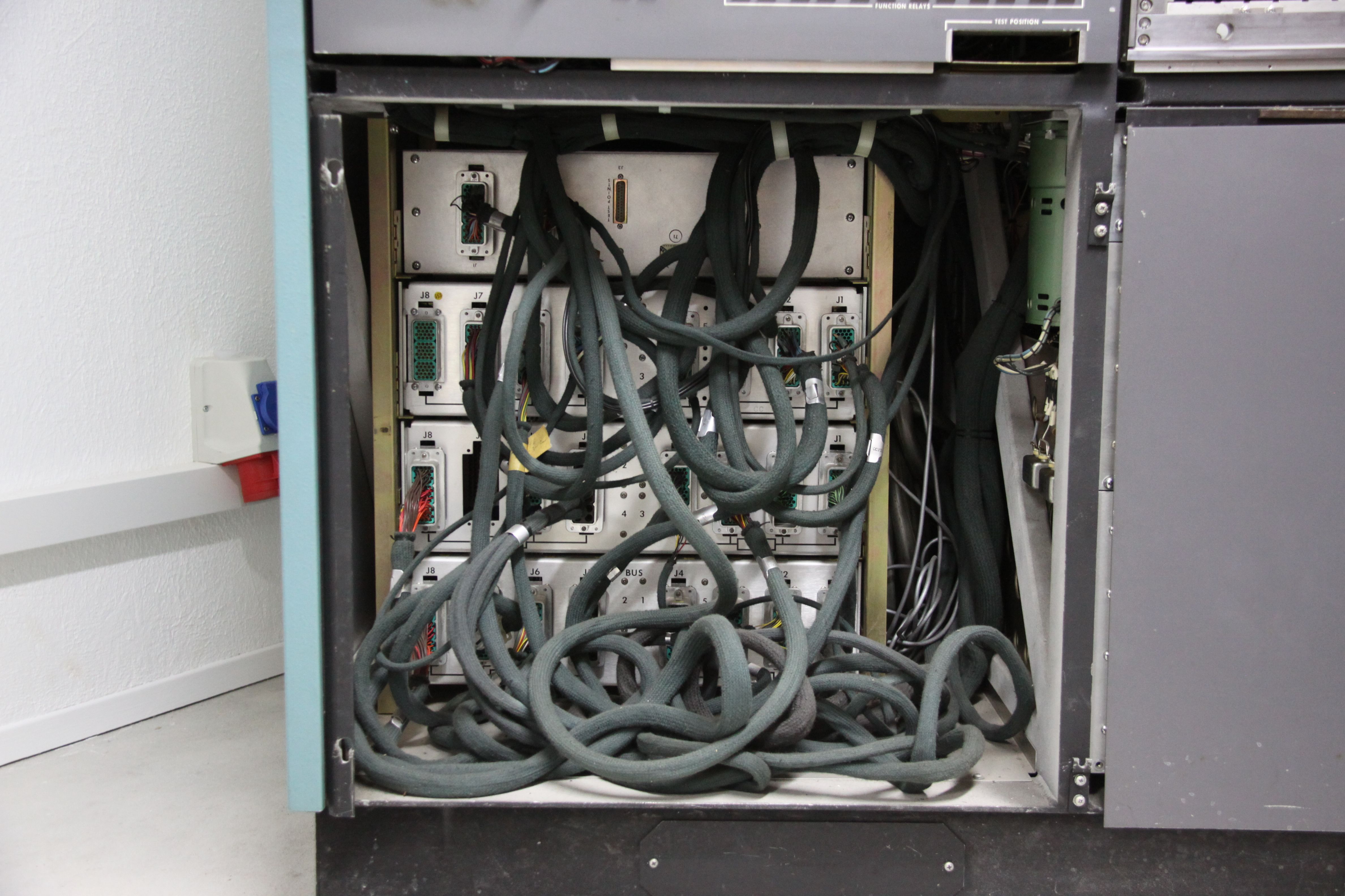
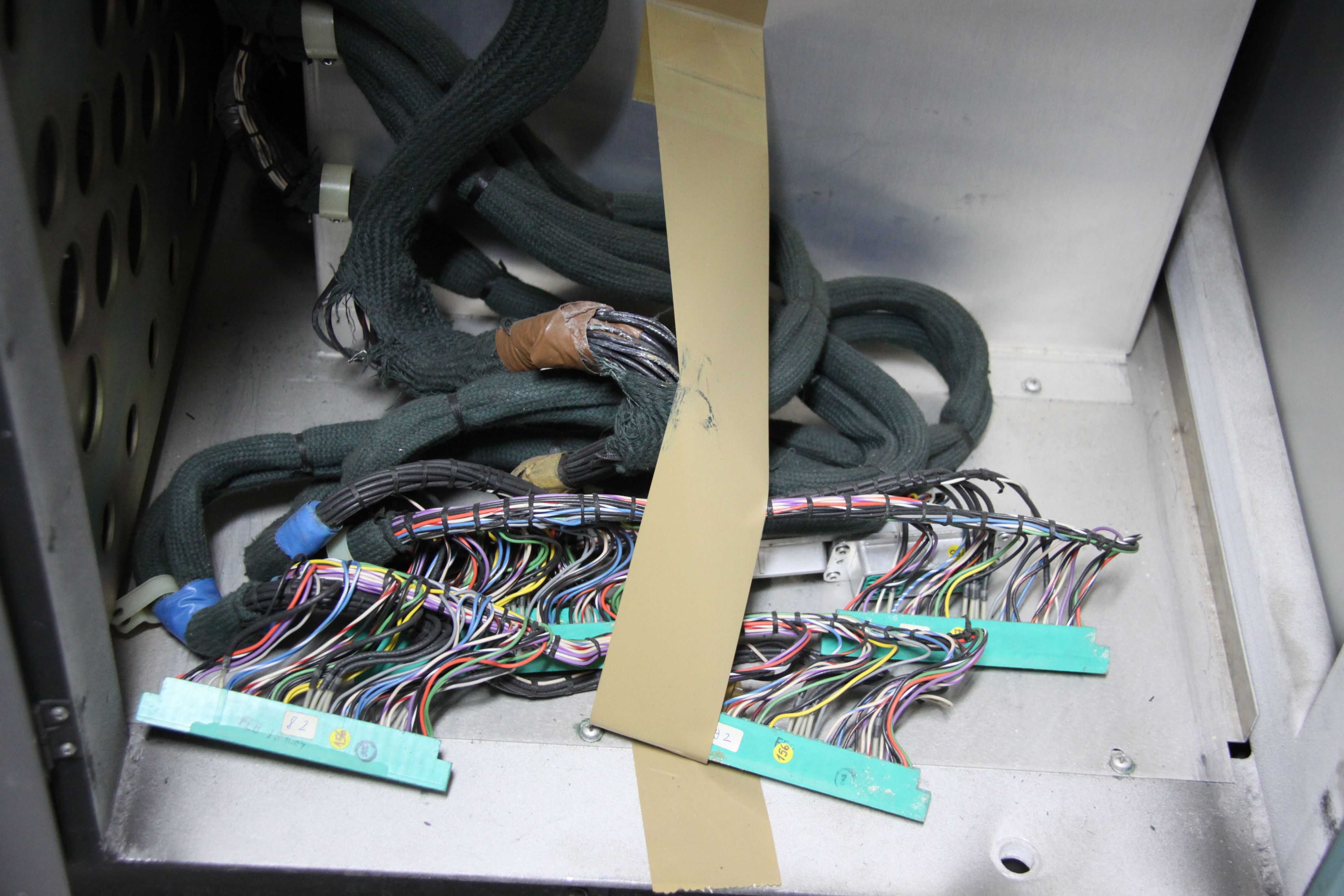
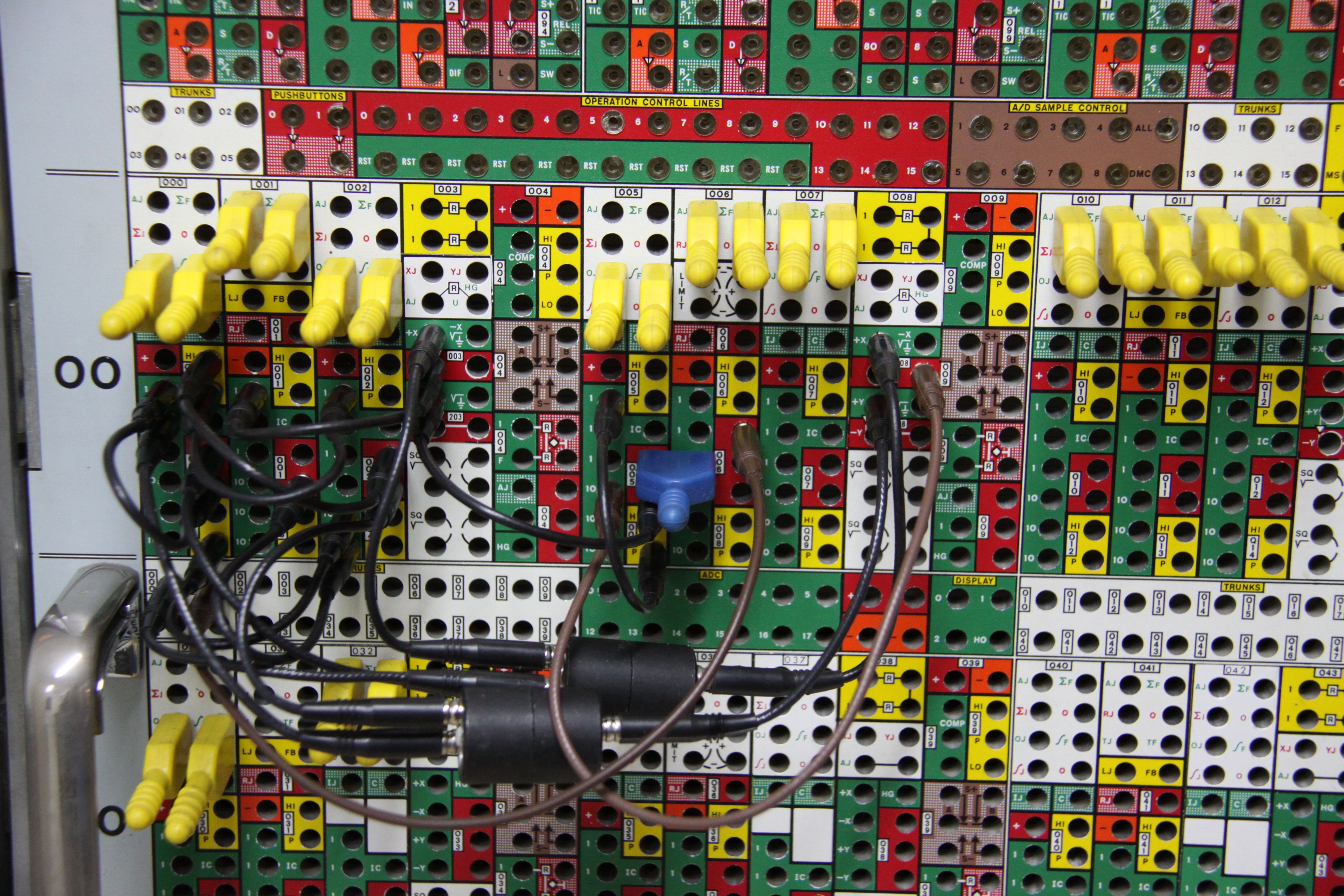
The following two pictures show the various interconnections in the control section (lower left of the machine) and the connections for the manual function generators and limiters (lower right of the machine). |
|
|
|
|
|
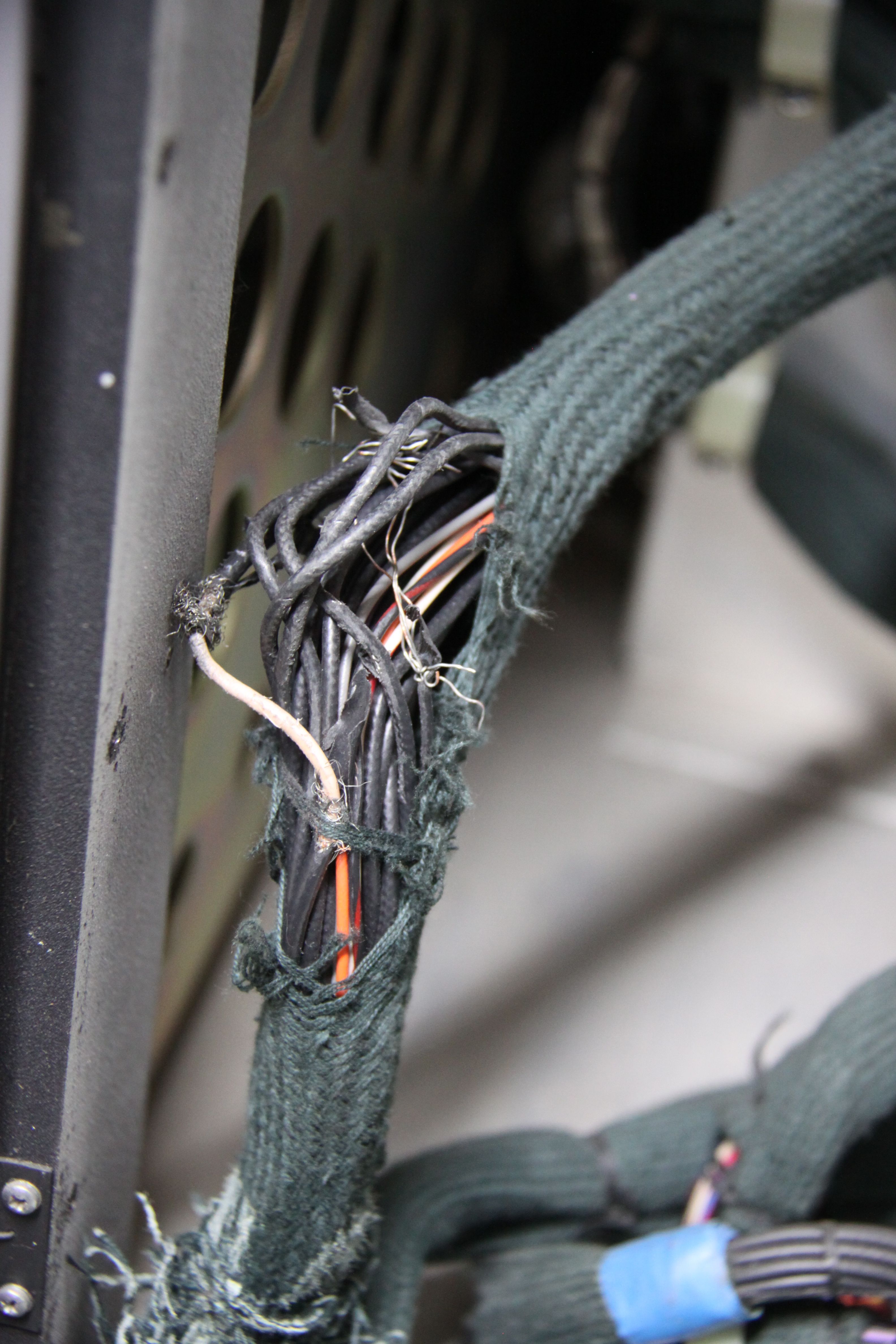
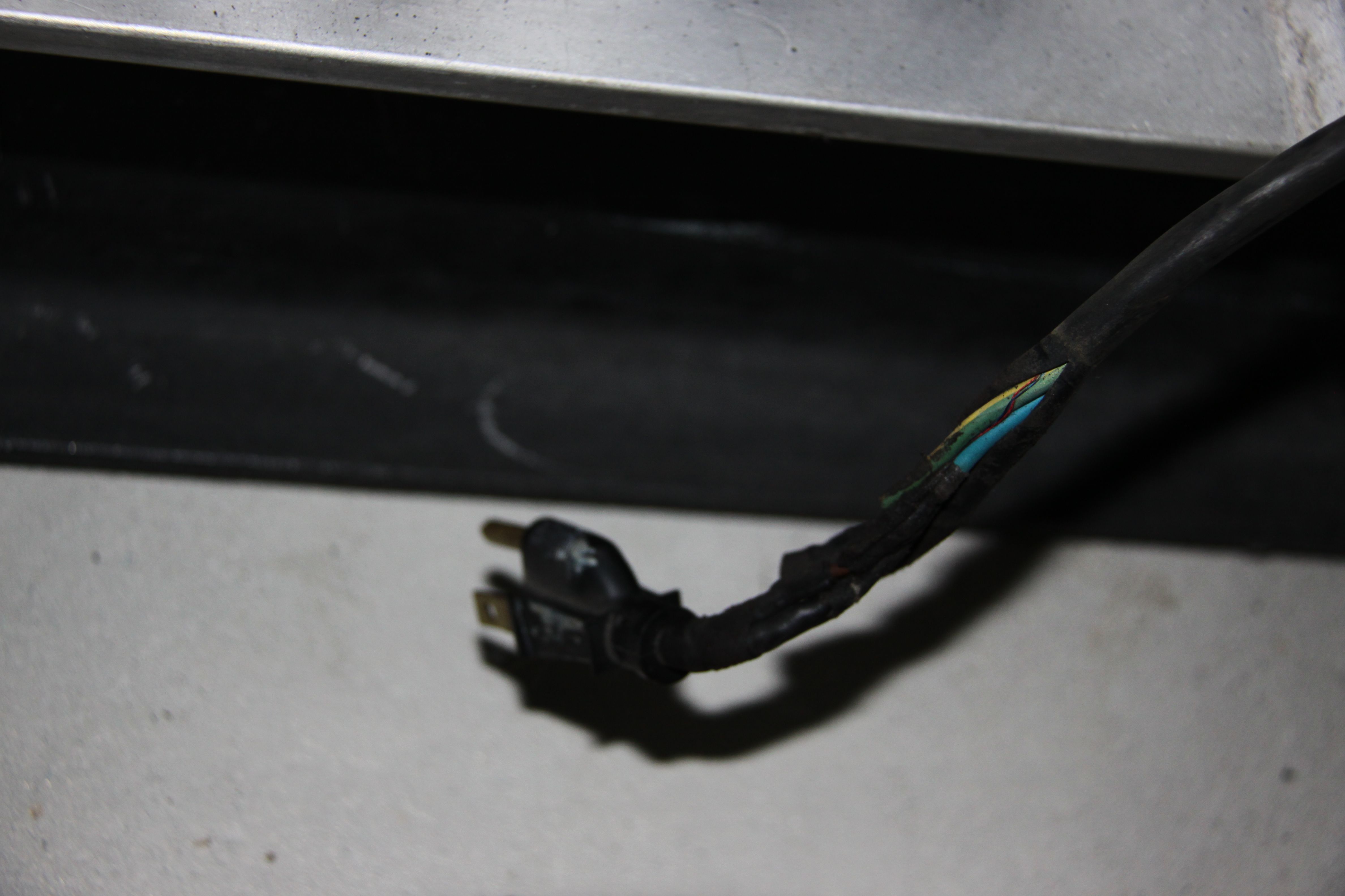
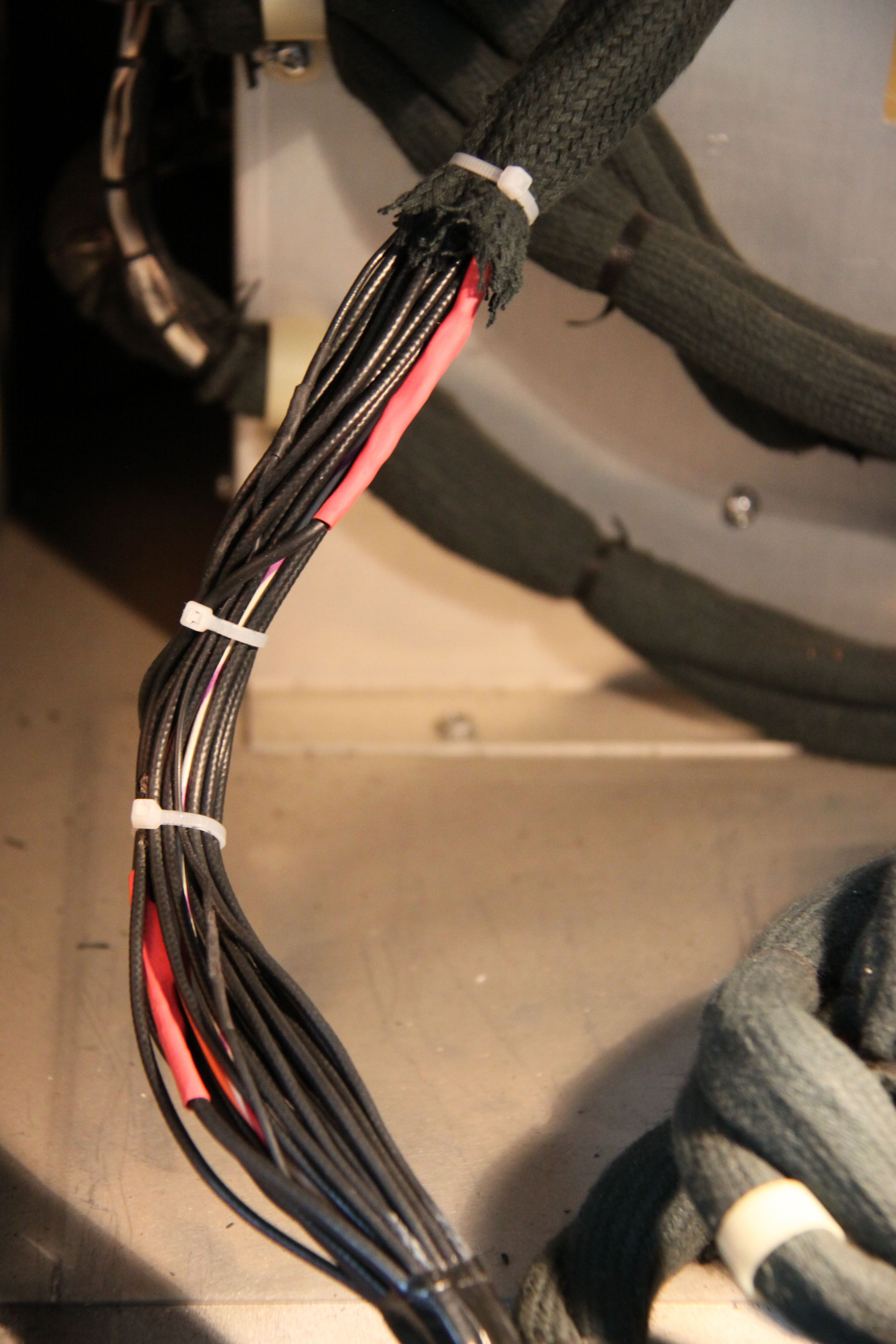
The next two pictures show typical examples of damaged cables in a 47 years old machine. These are prime candidates for the first repair session. |
|
|
|
|
|
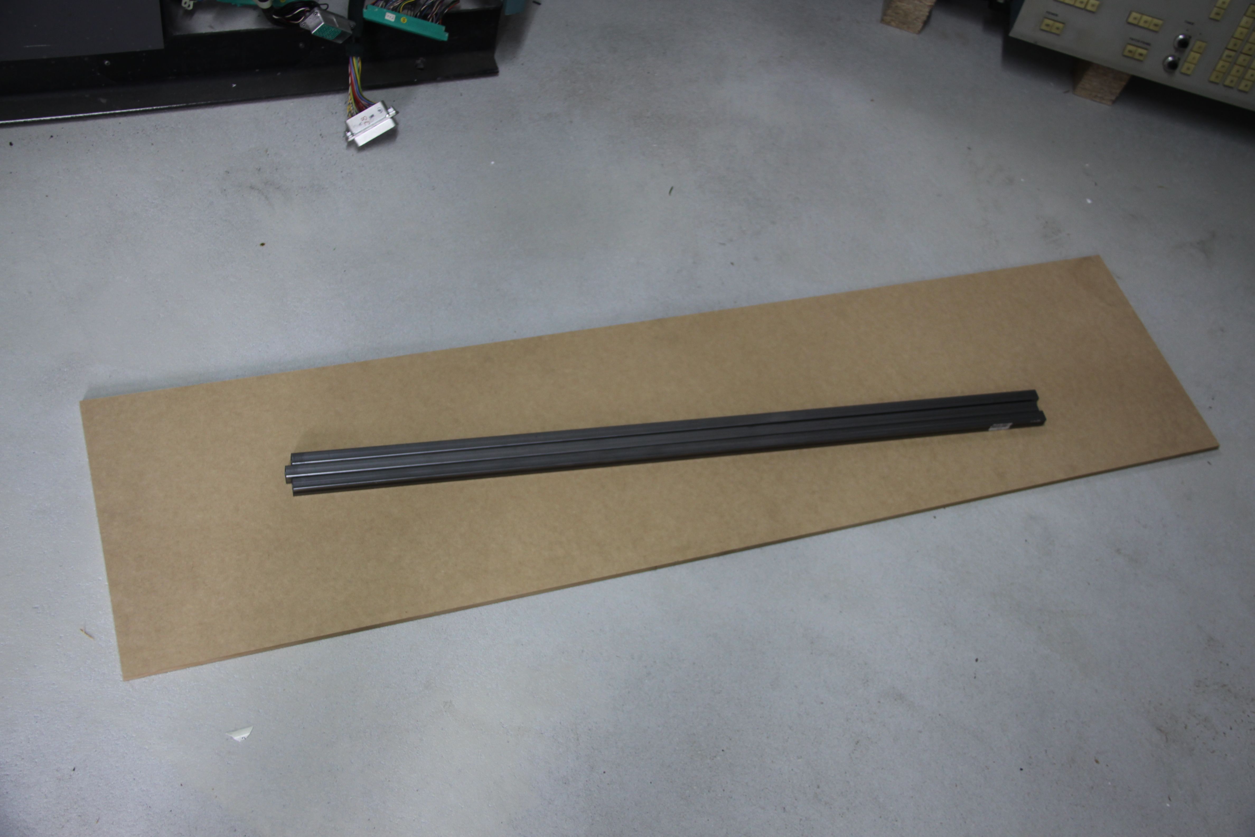
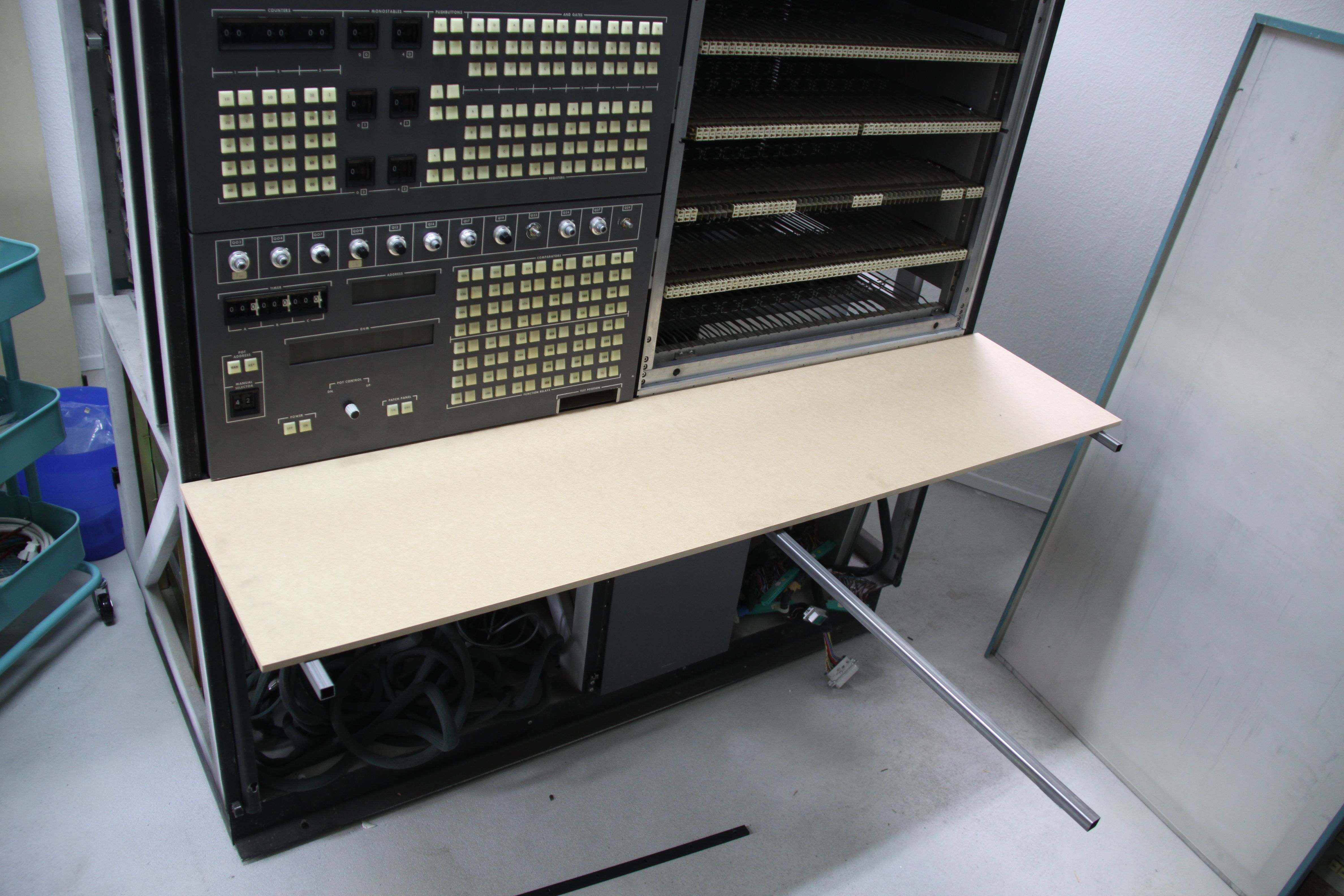
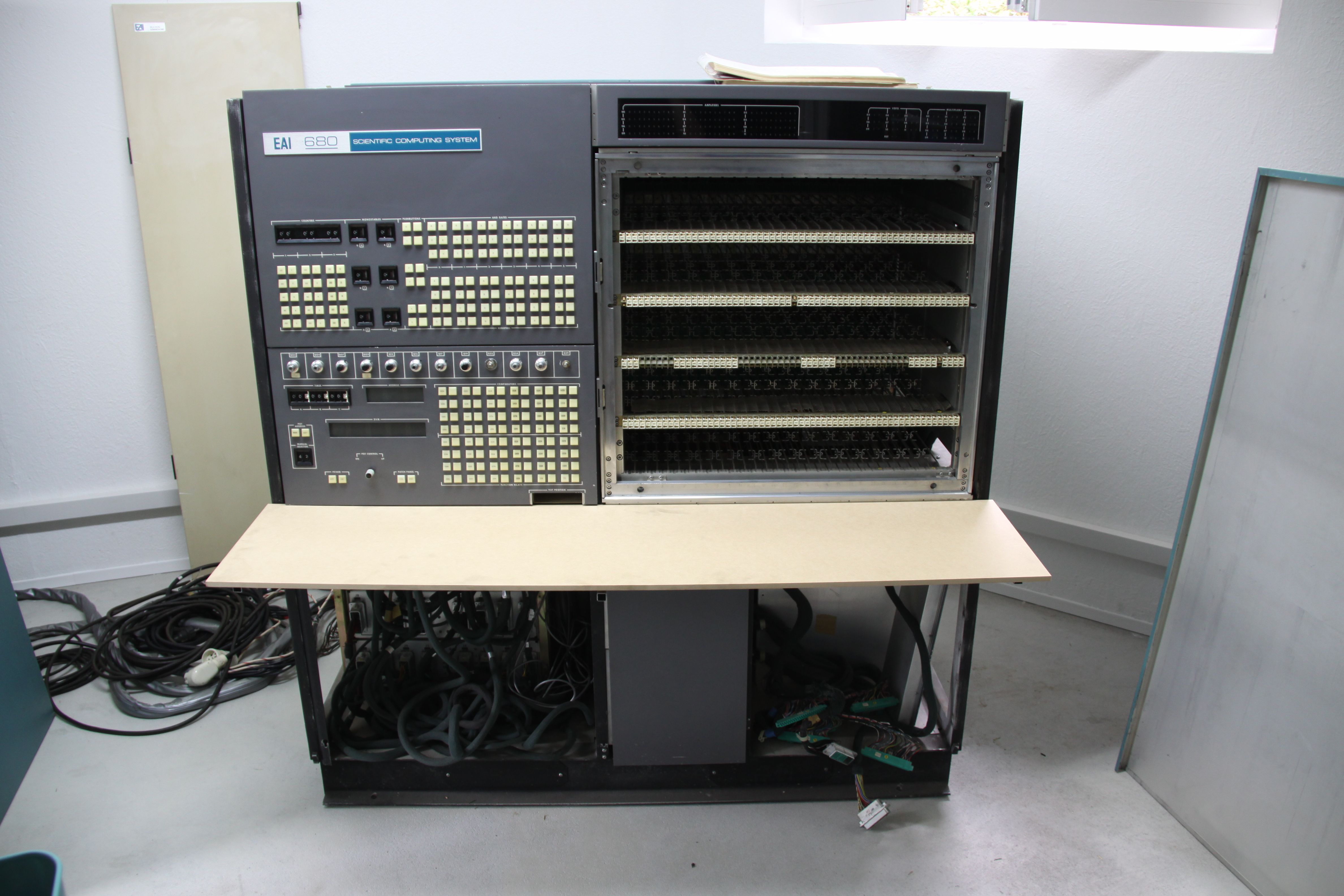
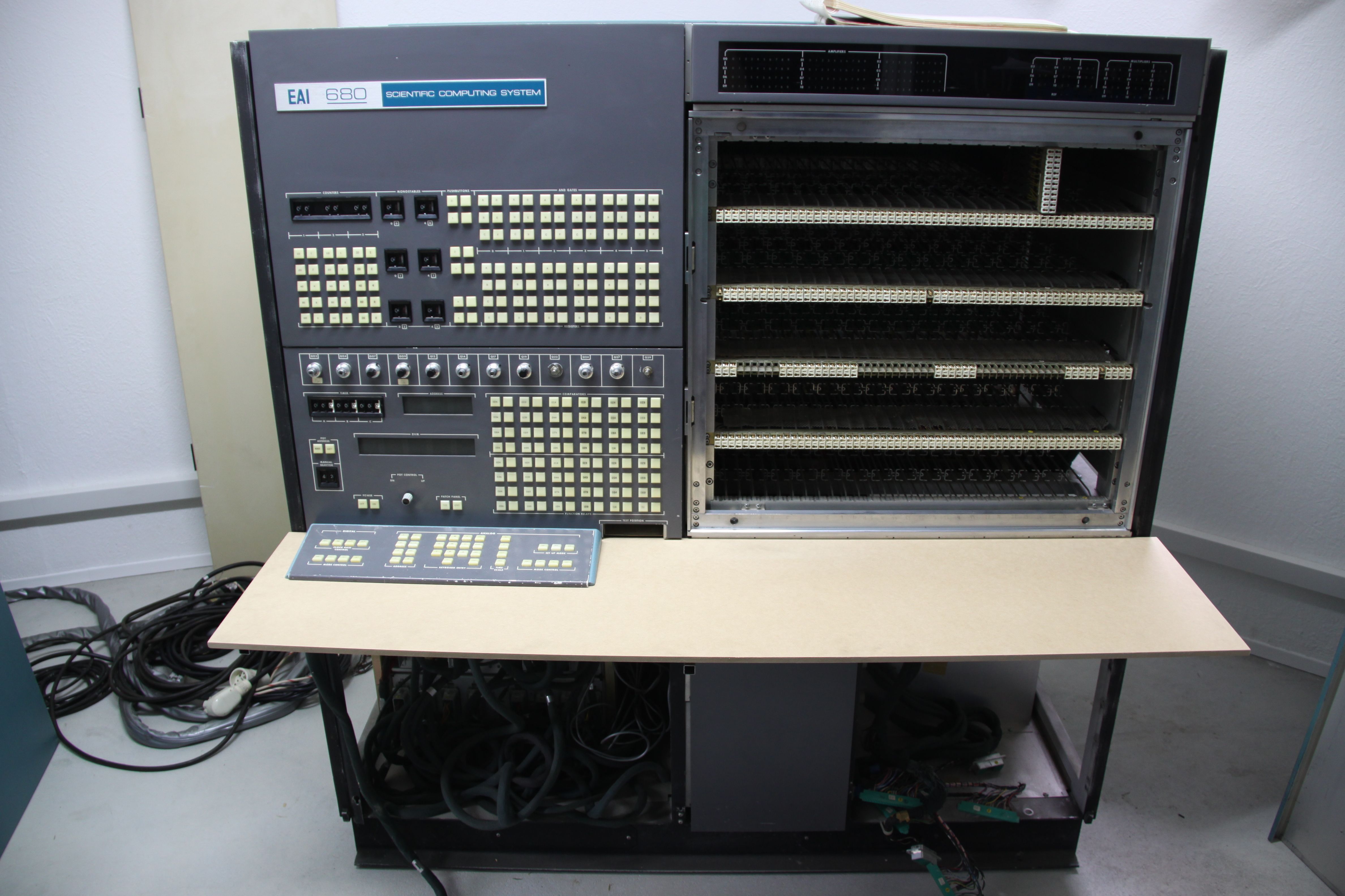
A prominent feature of the EAI 680 is its integrated desk holding a small manual control panel. Unfortunately the table plate of my machine is missing, so I had to make a new one. This will not be the final table plate but suffices for restauration process. When everything else is finished, I will mount a pretty varnished table plate but until then this simple sheet of plywood will do. The following four pictures show the steel bars I bought to mount the plate, the first try-on, the mounted plate, and the final configuration with the manual control panel installed. |
|
|
|
|
|
|
|
|
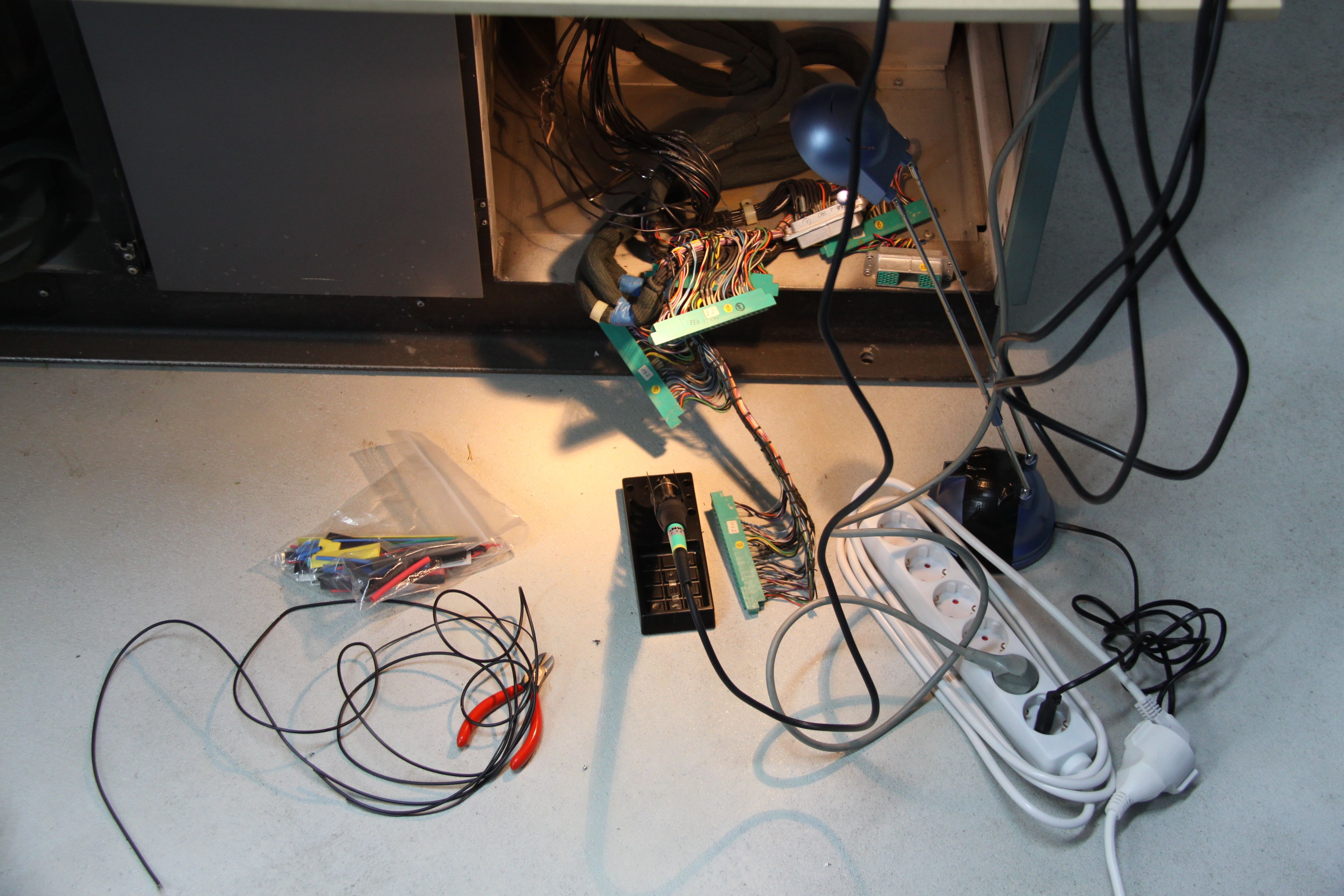
The next task was to repair the damaged cabling. The picture on the left shows the preparations for this task. The damaged sections of the coaxial and unshielded cables were cut, removed, and replaced by new cables. The picture on the rights shows the result - pretty, isn't it? |
|
|
|
|
|
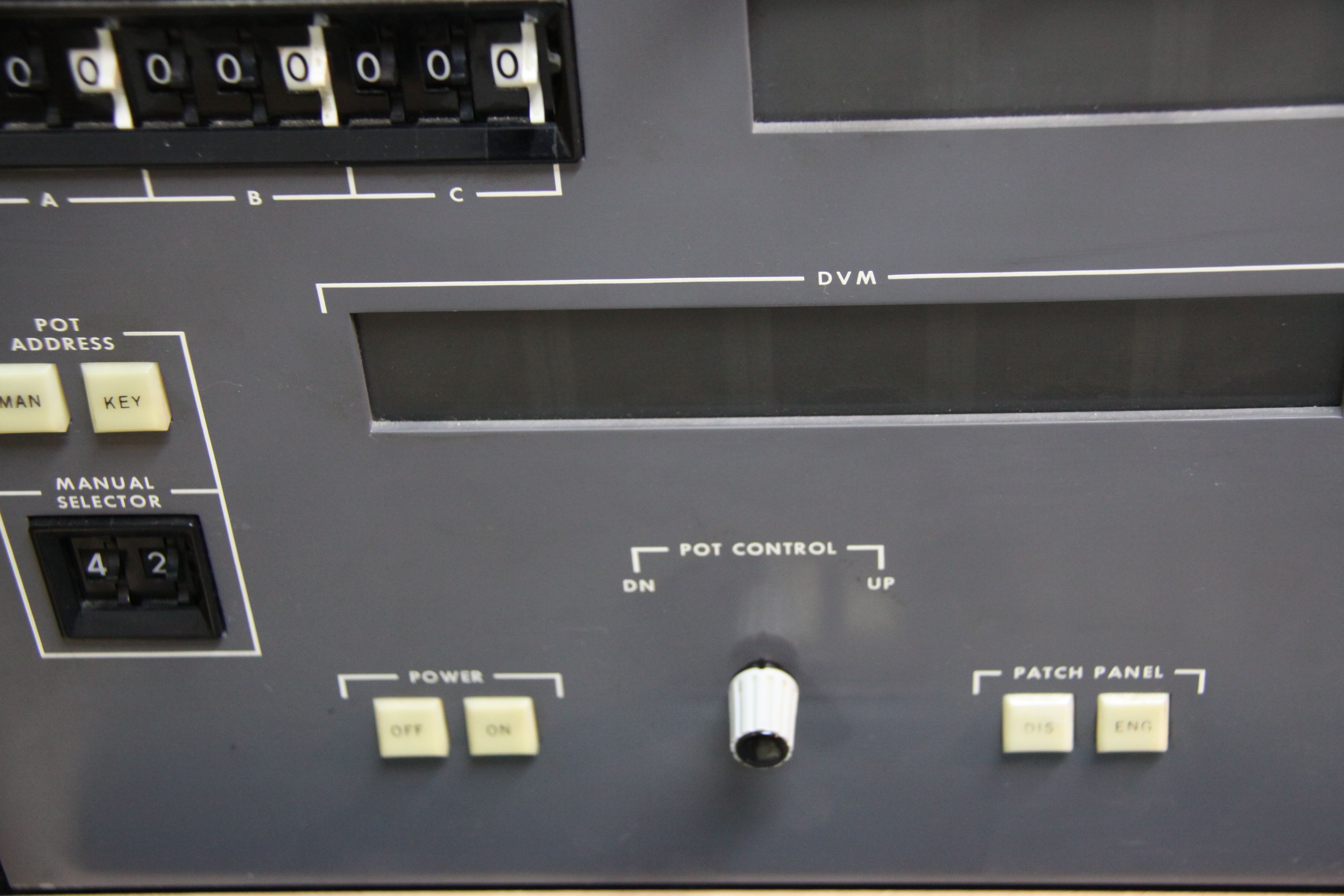
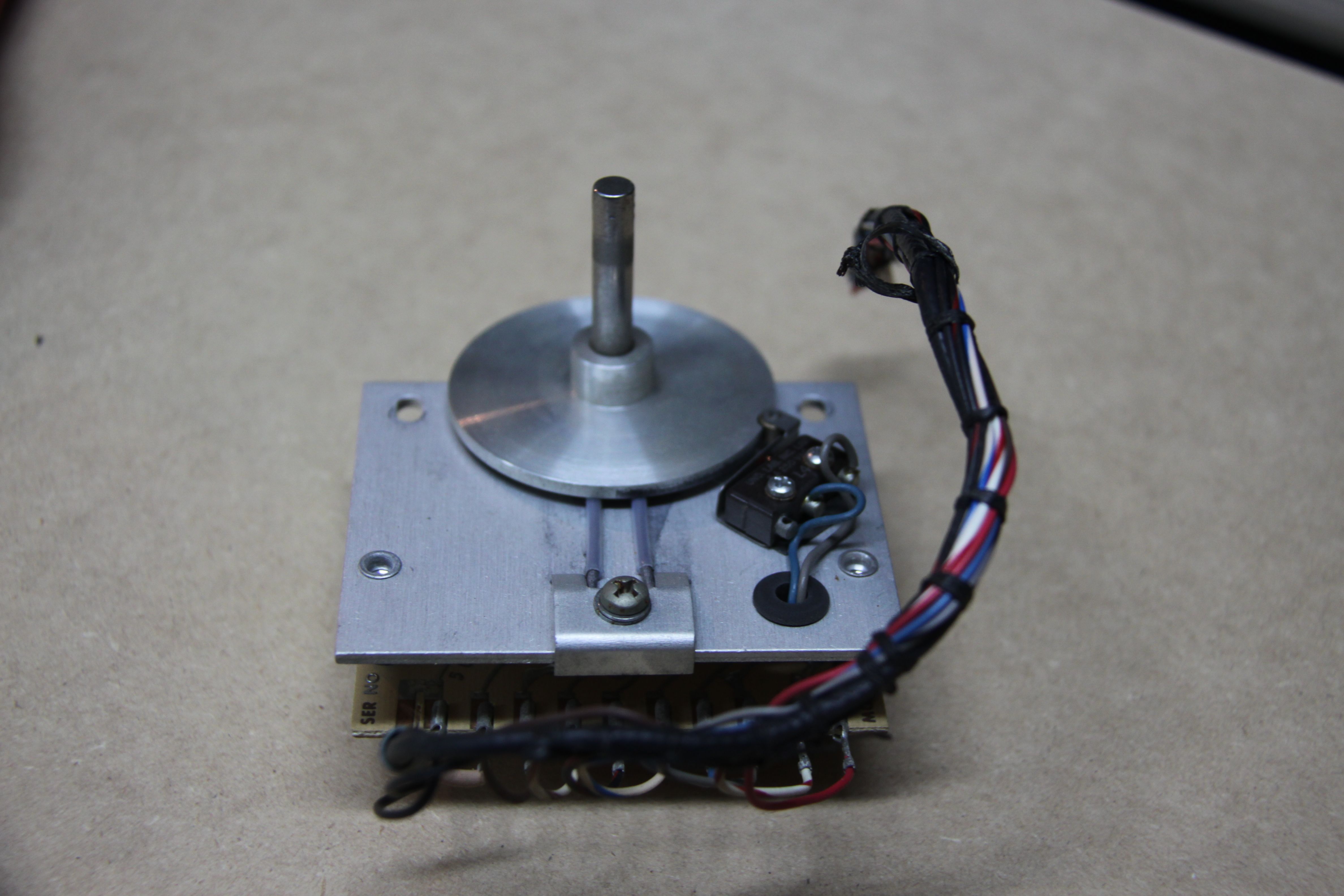
The next repair step was mainly cosmetic in its nature: The EAI 680 and EAI 580 both feature a lever to manually control selected servo potentiometers. This lever was missing on my machine and was too stiff to work properly. Fortunately, some years ago I was given a few remnants of an EAI 580 installation which had been scrapped in the 1990s (*sigh*). Among these parts was the required lever and a "new" control module. The picture on the right shows the lever replacement fitted by the previous owner, while the two pictures below show the replacement unit and the matching lever I installed. |
|
|
|
|
|
|
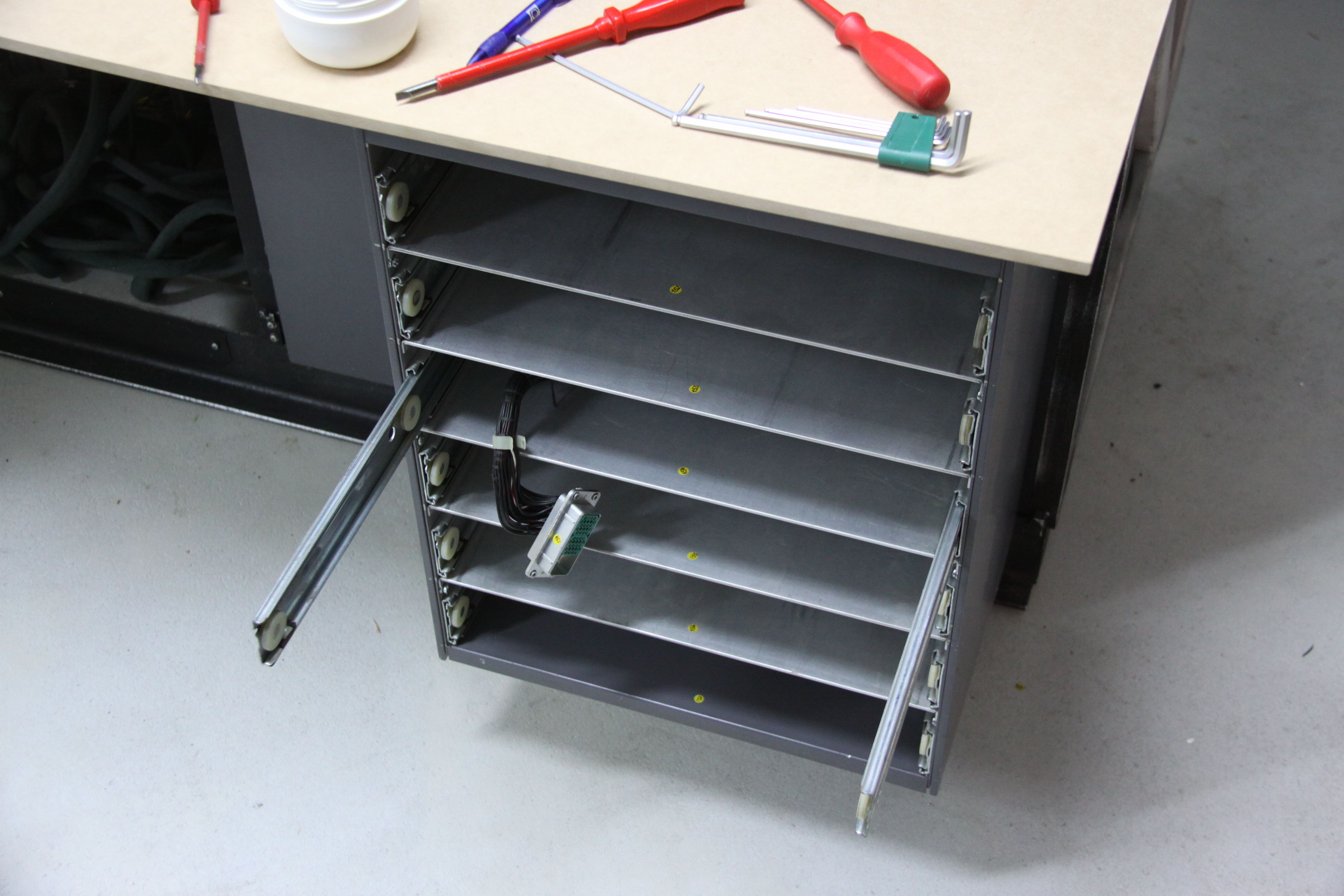
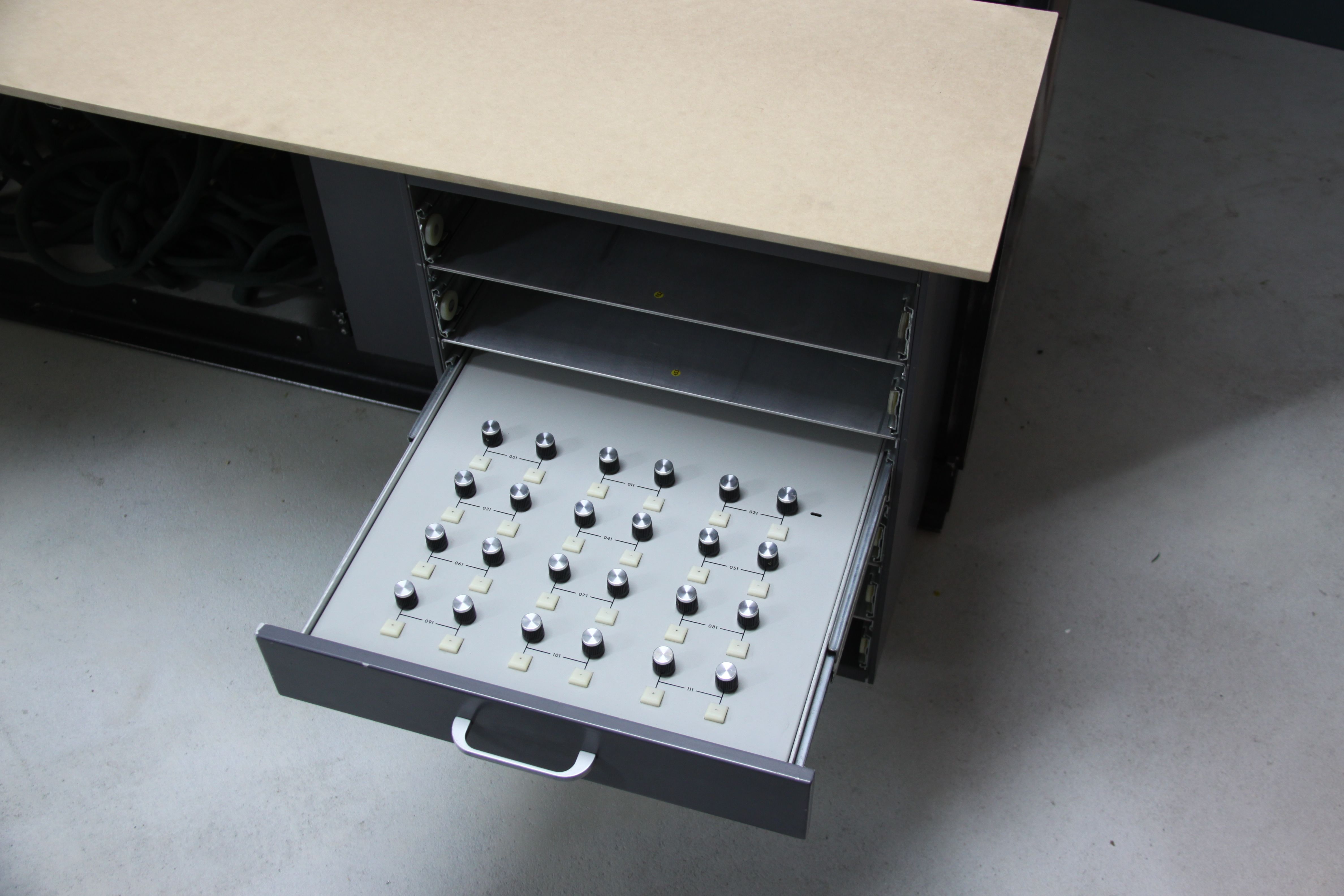
Fortunately, the drawer enclosure to be mounted under the table plate on the right of the EAI 680 had not been lost, so I could now mount it on the main frame. I have to admit that I cursed the EAI engineers more than once during this procedure. The drawer is a bit narrower than its reserved space in the machine. So one needs a steel bar to make up for the difference in width. Although I had a perfectly fitting steel bar it took literally hours to get everything aligned correctly. The task of refitting the drawer box was further complicated by the fact that some of the screw threads in the metal frame had been damaged at some point in the past, so I had to redo some of these threads as well... All in all this seemingly simple task took the better part of a whole night. The two pictures below show the result with the limiter drawer already installed. |
|
|
|
|
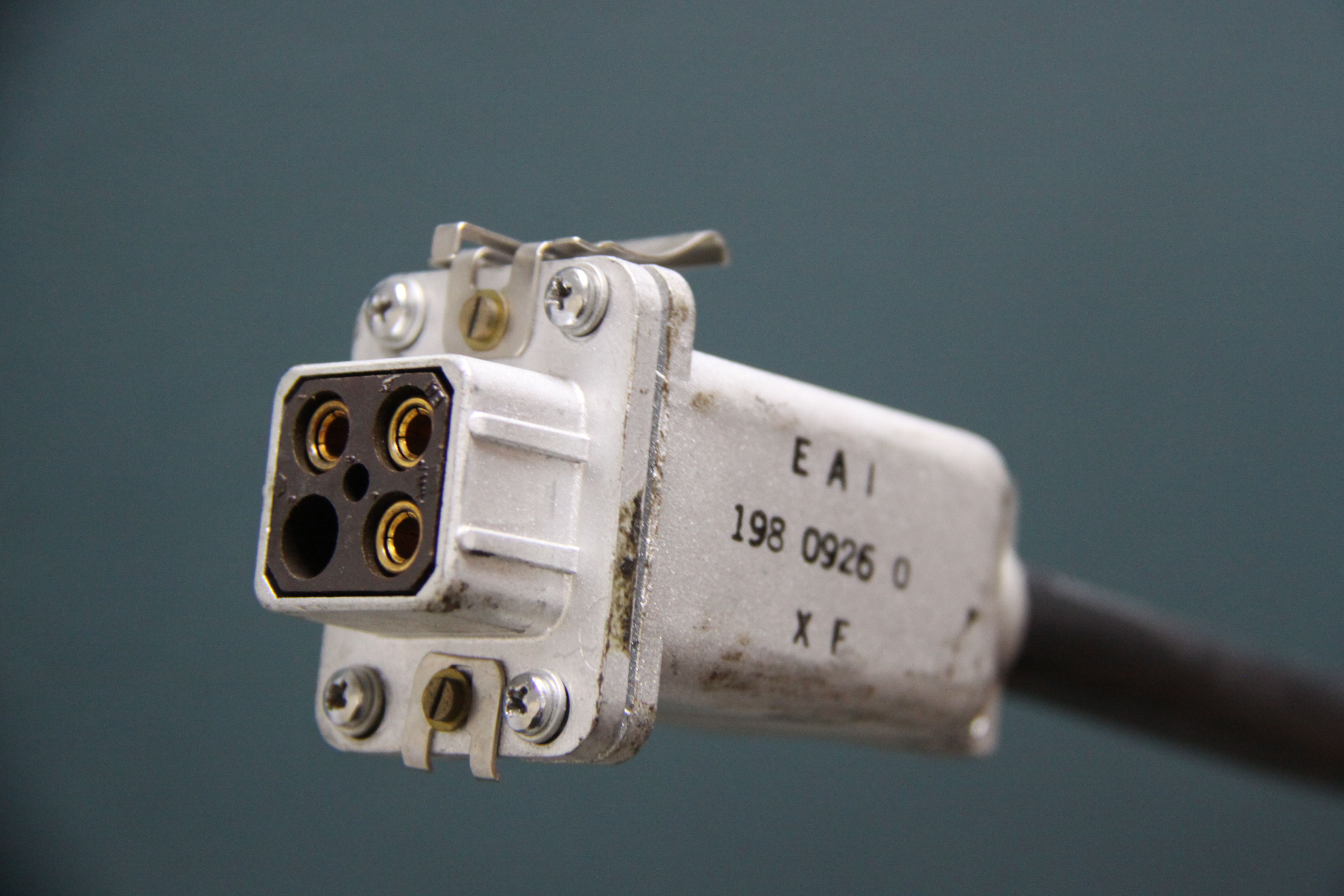
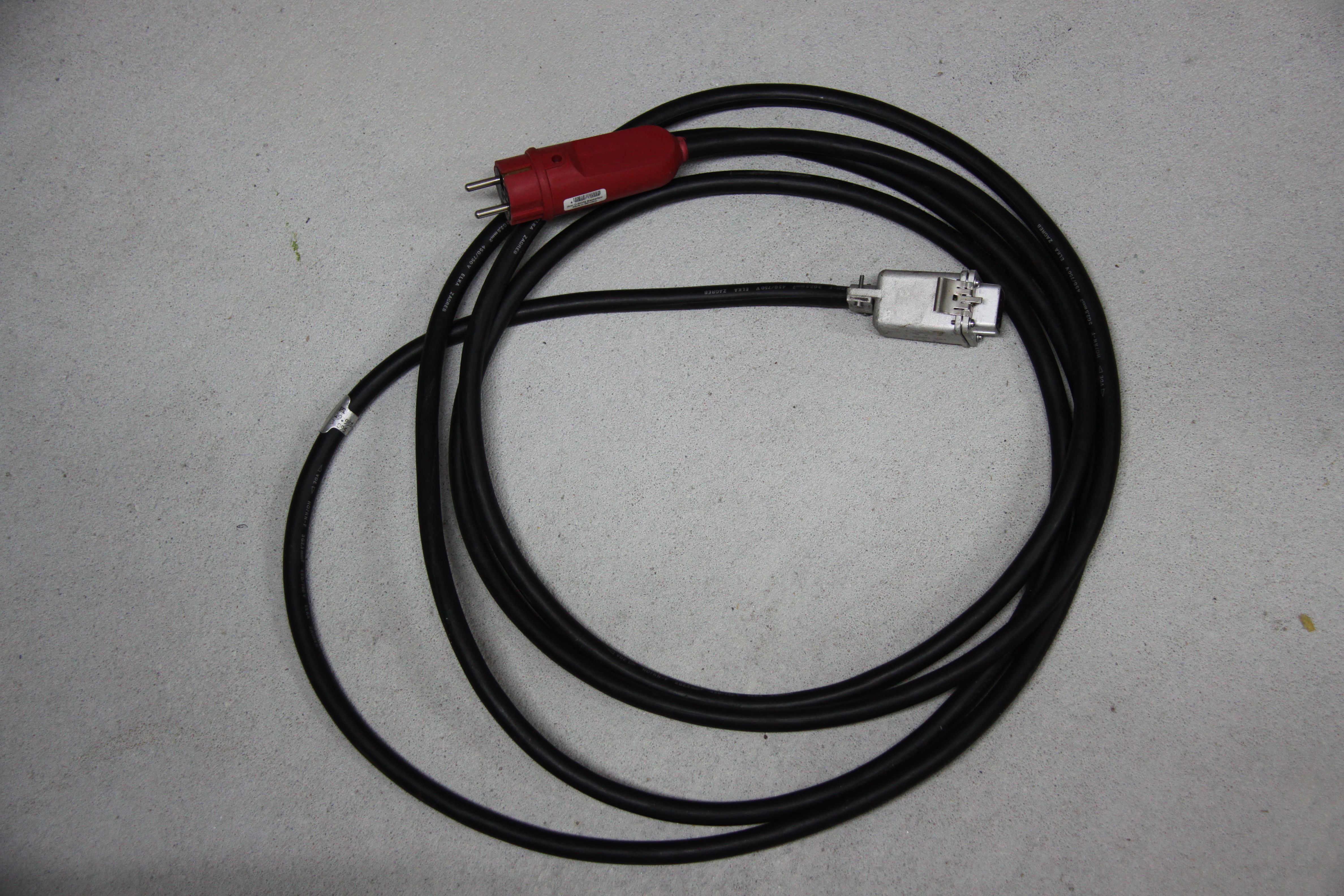
As I am an incredible pack rat, I had a fitting power plug to make a power cable for the machine. The picture on the left shows the (rather arcane as I think) plug used by EAI and the finished cable. |
|
|
|
|
|
|
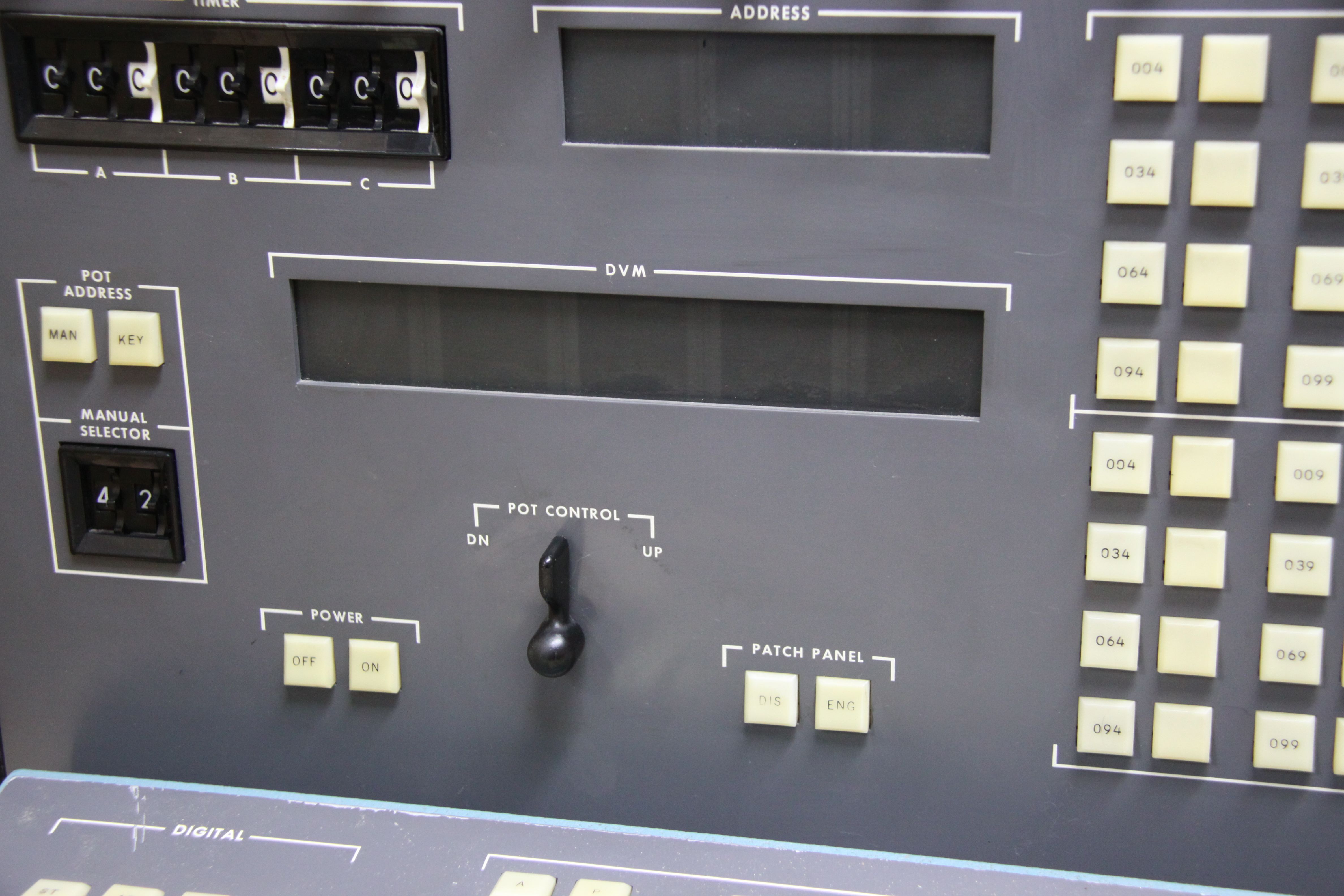
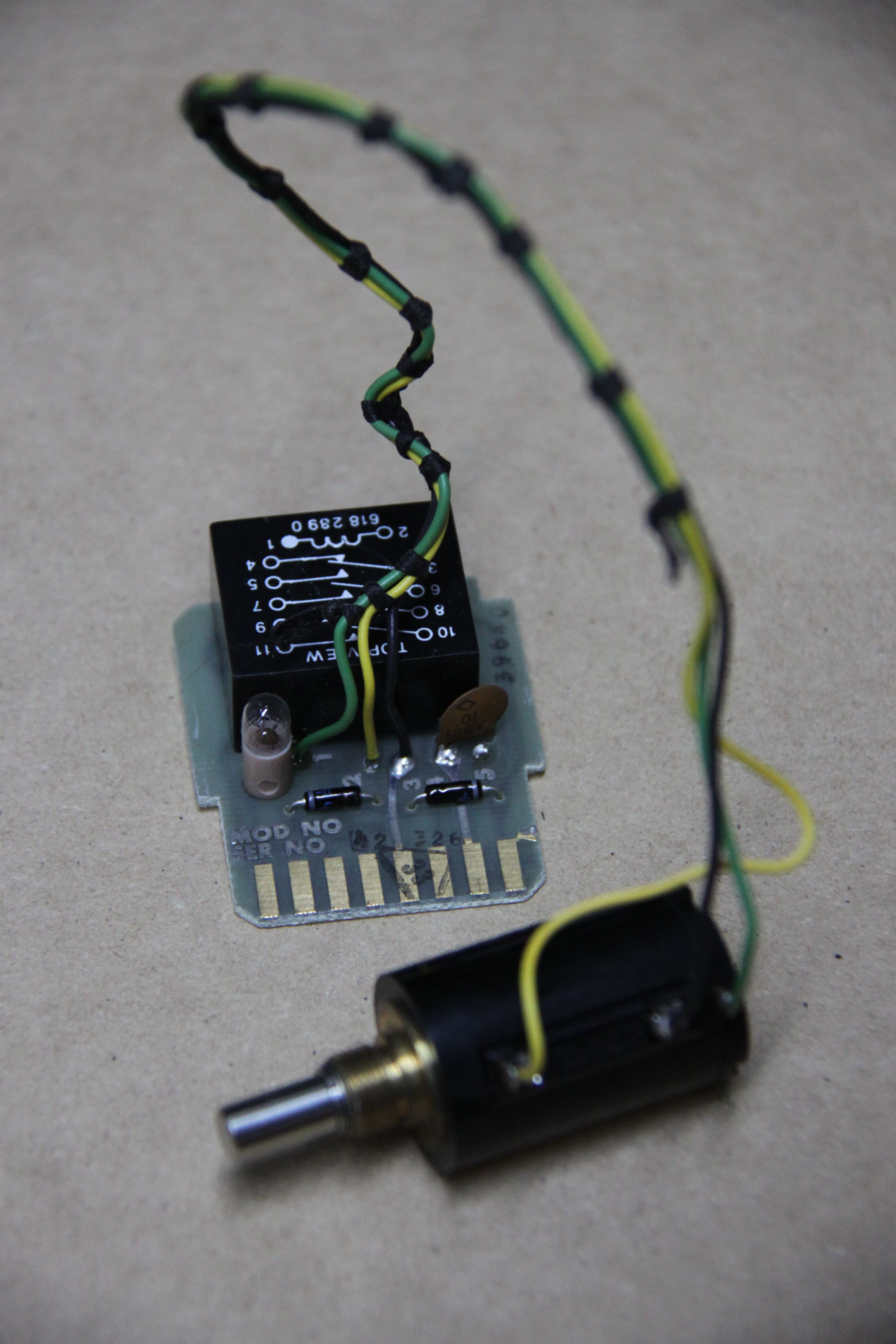
The next step was repairing the manual potentiometers mounted on the central control panel. Some potentiometers were just missing their precision knobs while others were stuck or otherwise defective. The picture on the left shows these potentiometers in detail. They can be reached from behind the front door after removing a steel plate. The picture below left shows a modern replacement potentiometer connected to the small circuit board holding the readout and setup relay and a small incandescent lamp. This lamp protects the wiper from excessive currents caused by wrong patching. The picture on the right shows the result of this work (unfortunately, I did not have enough knobs of the same style, so it looks not as uniform as it should). |
|
|
|
|
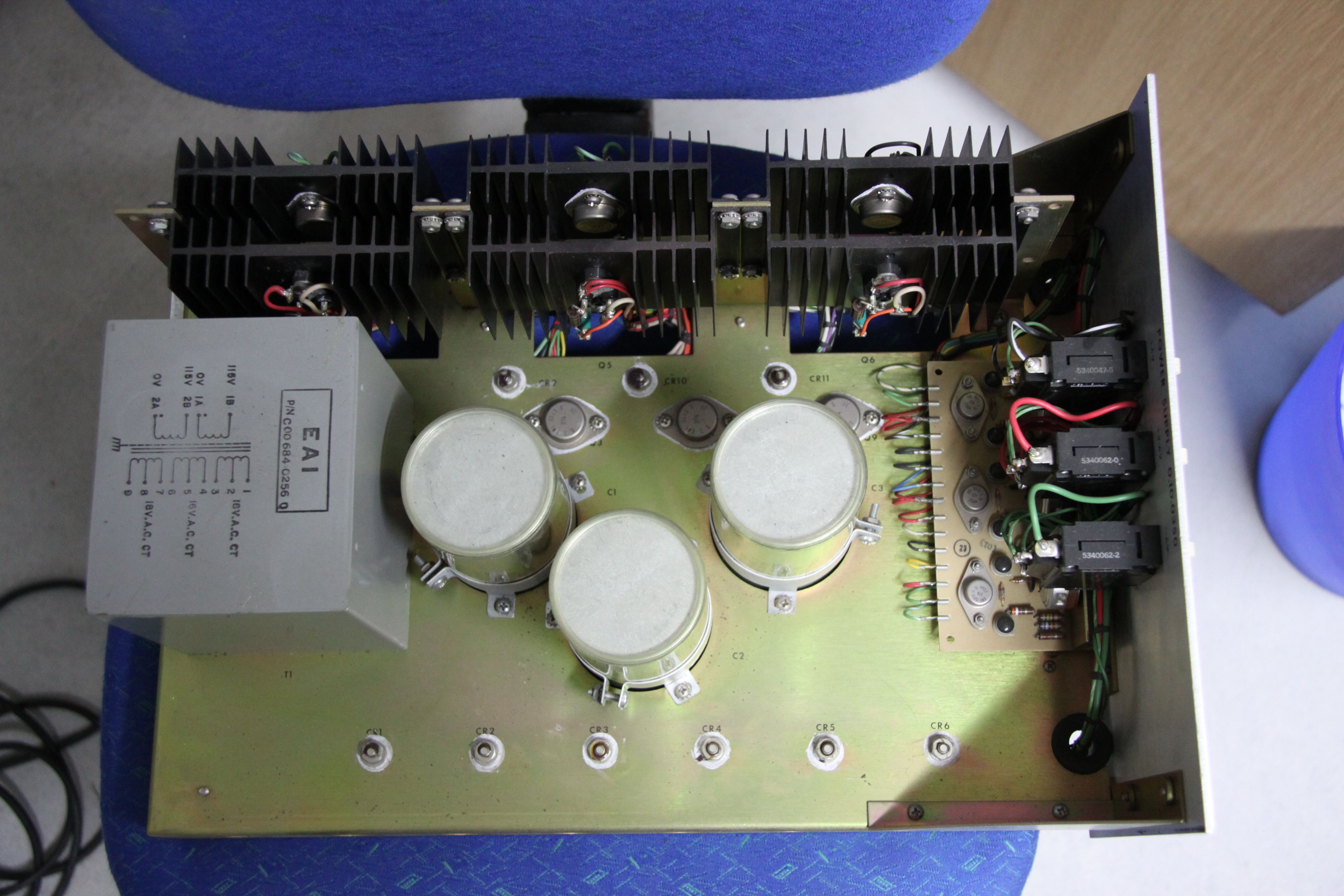
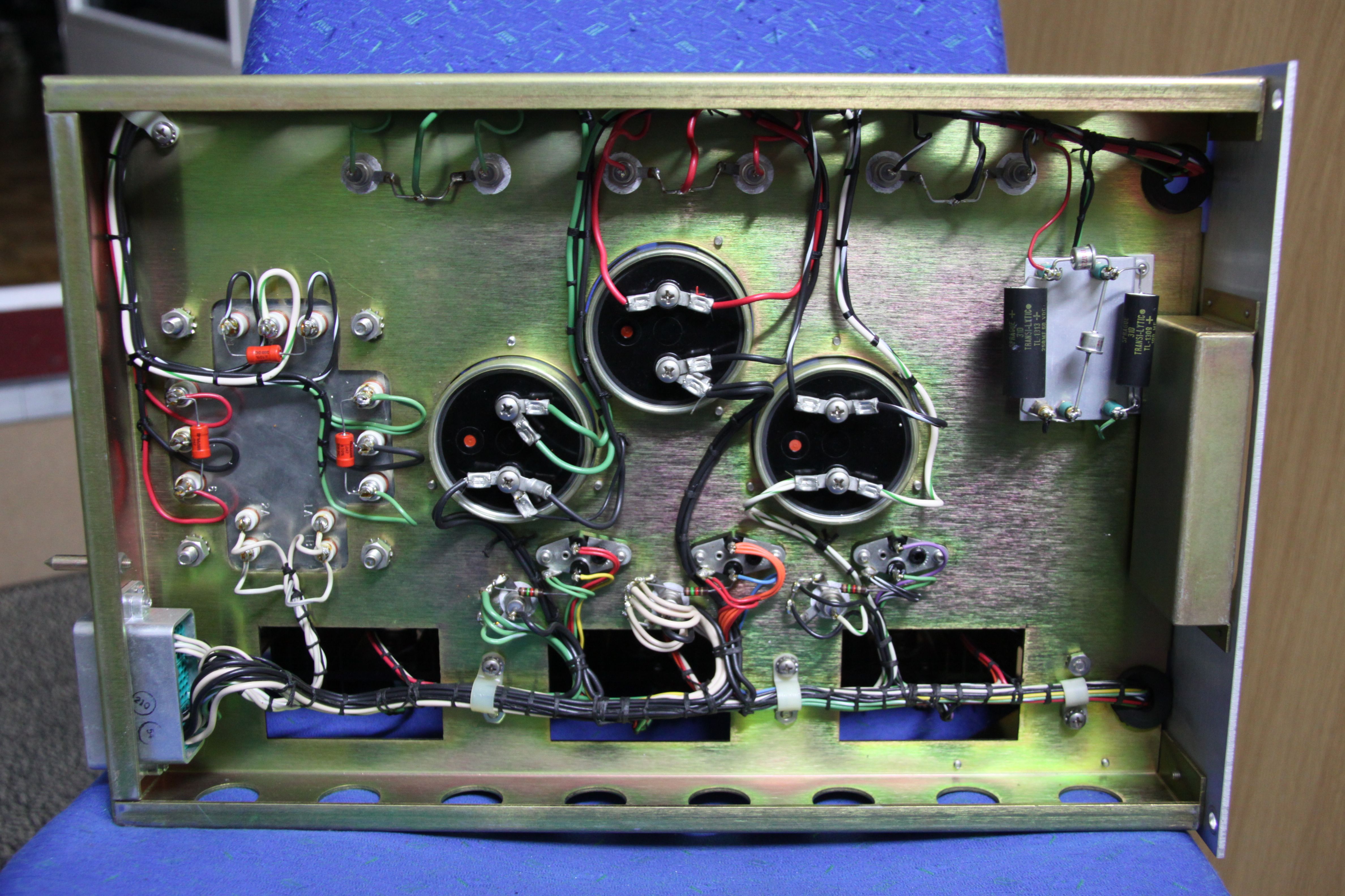
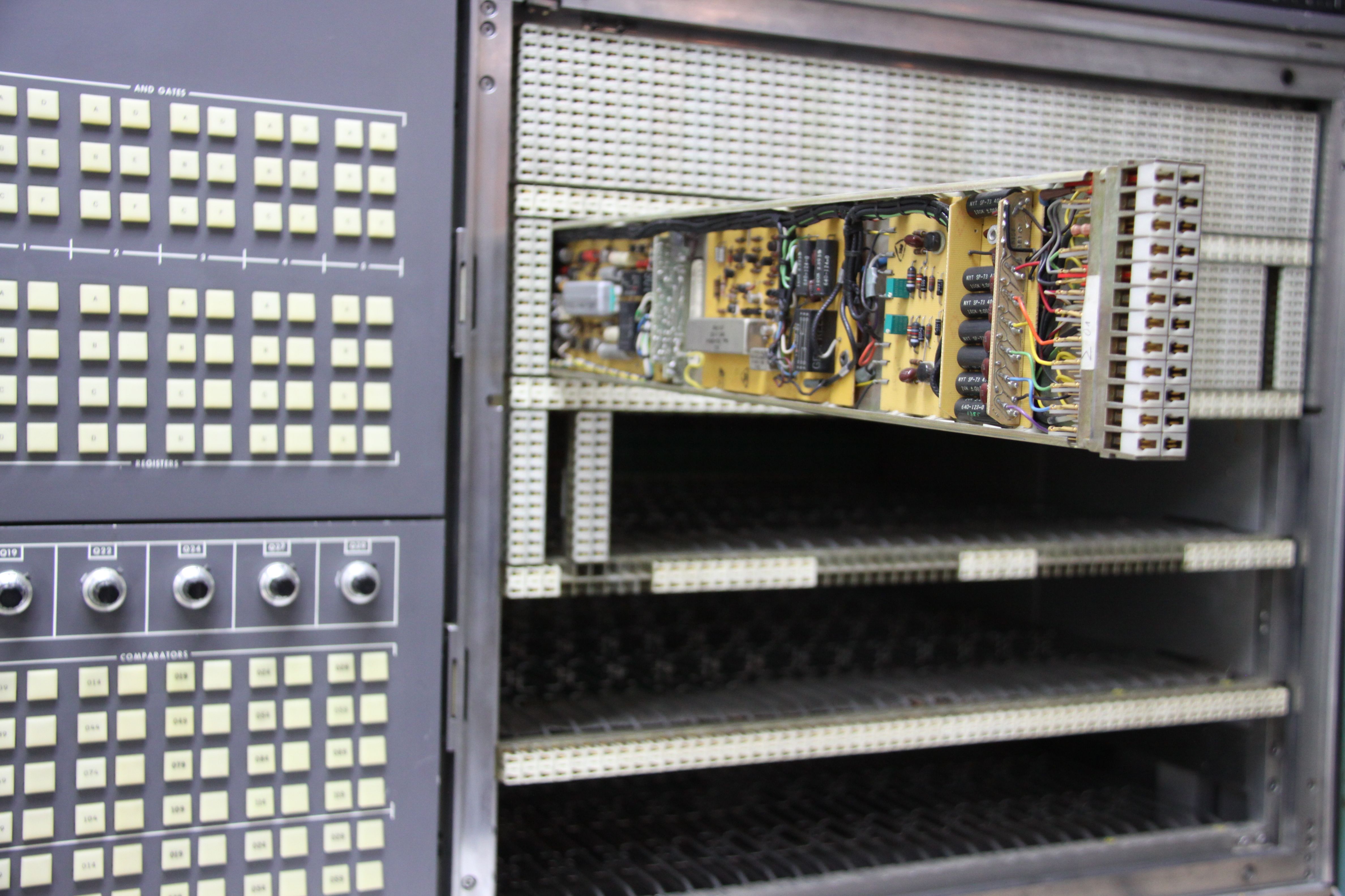
Now that all obvious and cosmetic problems had been solved, the time for testing the power supplies had come. Since all power supplies in the EAI 680 are linearly regulated, there is no need for a base load, simplifying things quite a bit. First of all I removed all circuit boards to make sure that nothing could be damaged by a faulty power supply. What really amazed me was that all power supplies for the analog section were still within their specifications! Even the high-precision supplies for the +/-10 V machine units were within 1 mV! Nevertheless, one of the power supplies for the digital control circuitry was faulty. The 3.6 V supply delivered only about 3.12 V. At least this voltage was stable and did not change substantially under varying load. The picture on the left below shows the machine during its first power-on (the analog patch panel had been installed to check the interlock circuit and the motor-driven engage/disengage mechanics. The next picture shows the top of the power supply for the control circuitry. This frame contains an (extremely) heavy transformer with three associated linear regulators delivering +6 V, -6 V and 3.6 V. The following picture shows the bottom of this power supply. It turned out that one resistor in the sense-path of the 3.6 V linear regulator had changed its value. After replacing it the voltage was back in spec again as shown in the fourth picture with a reading of 3.55 V under full load. |
|
|
|
|
|
|
|
|
|
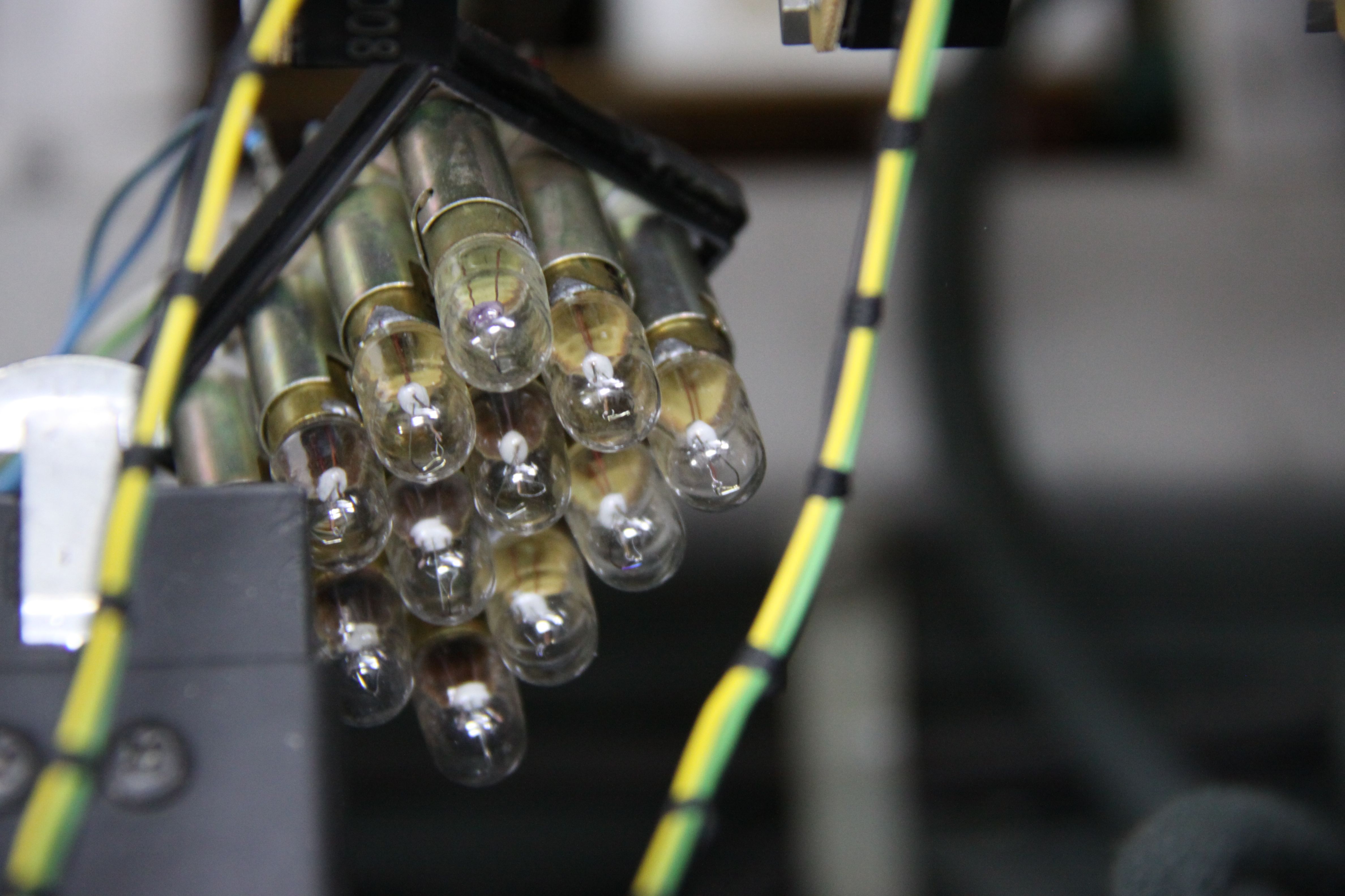
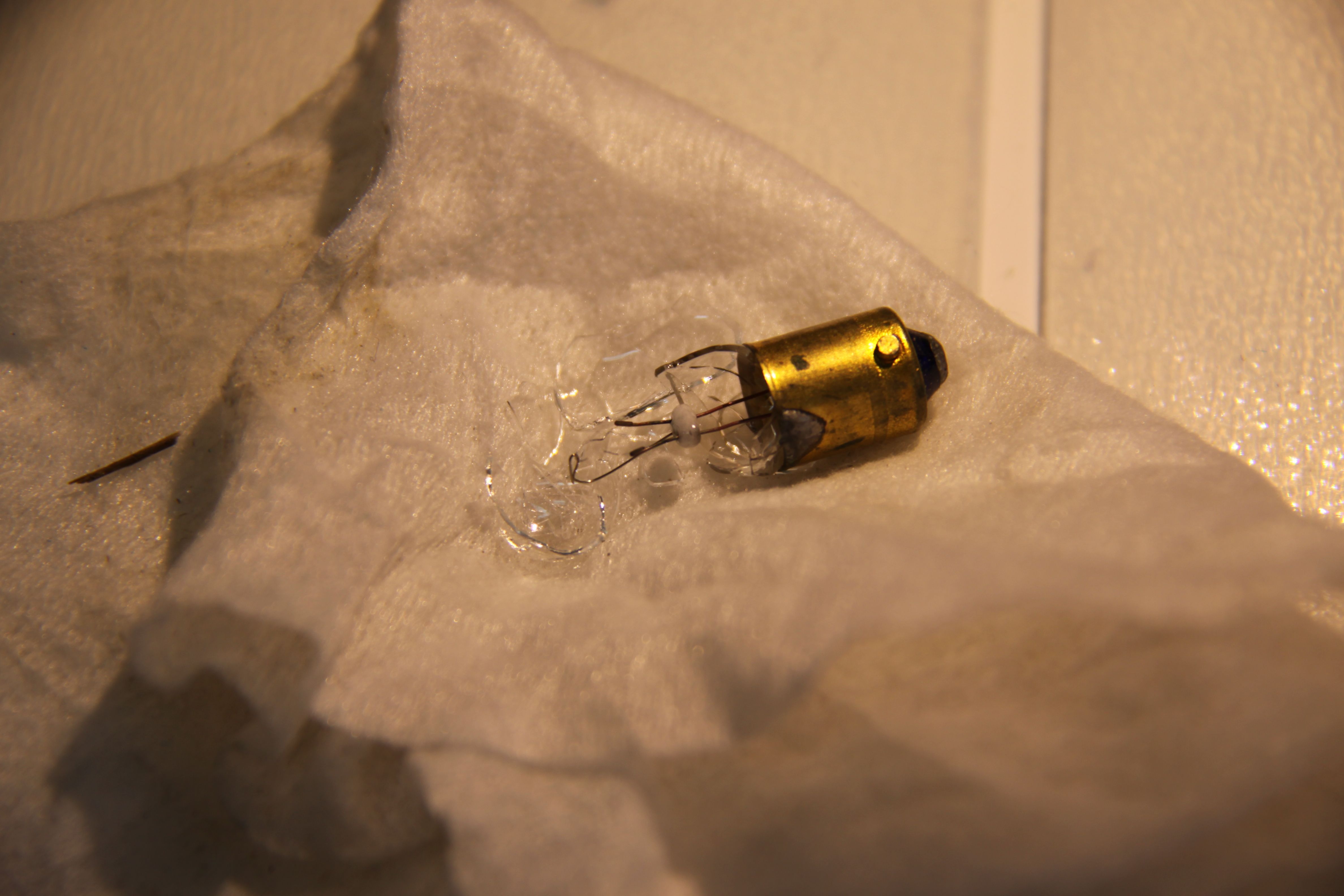
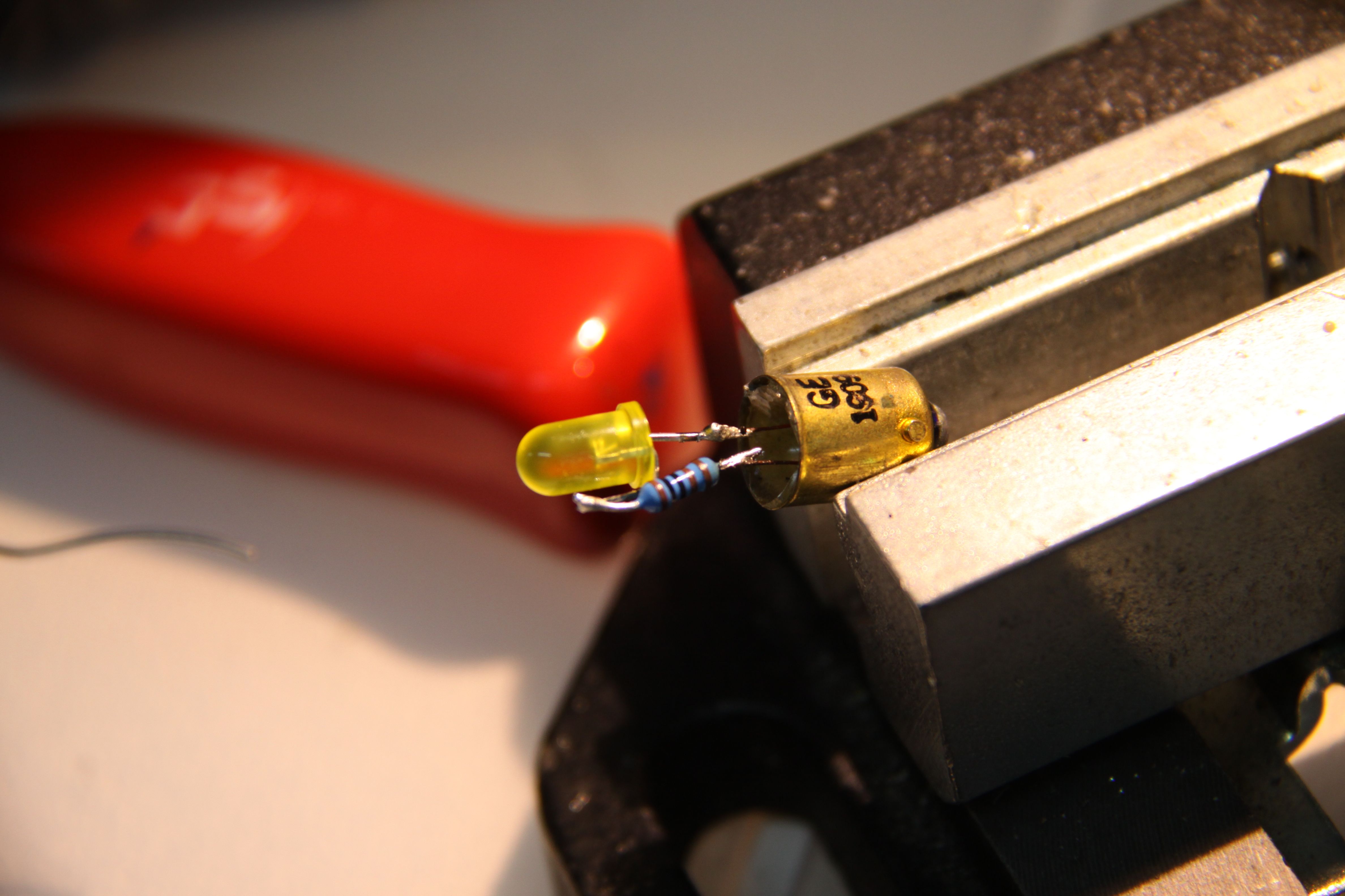
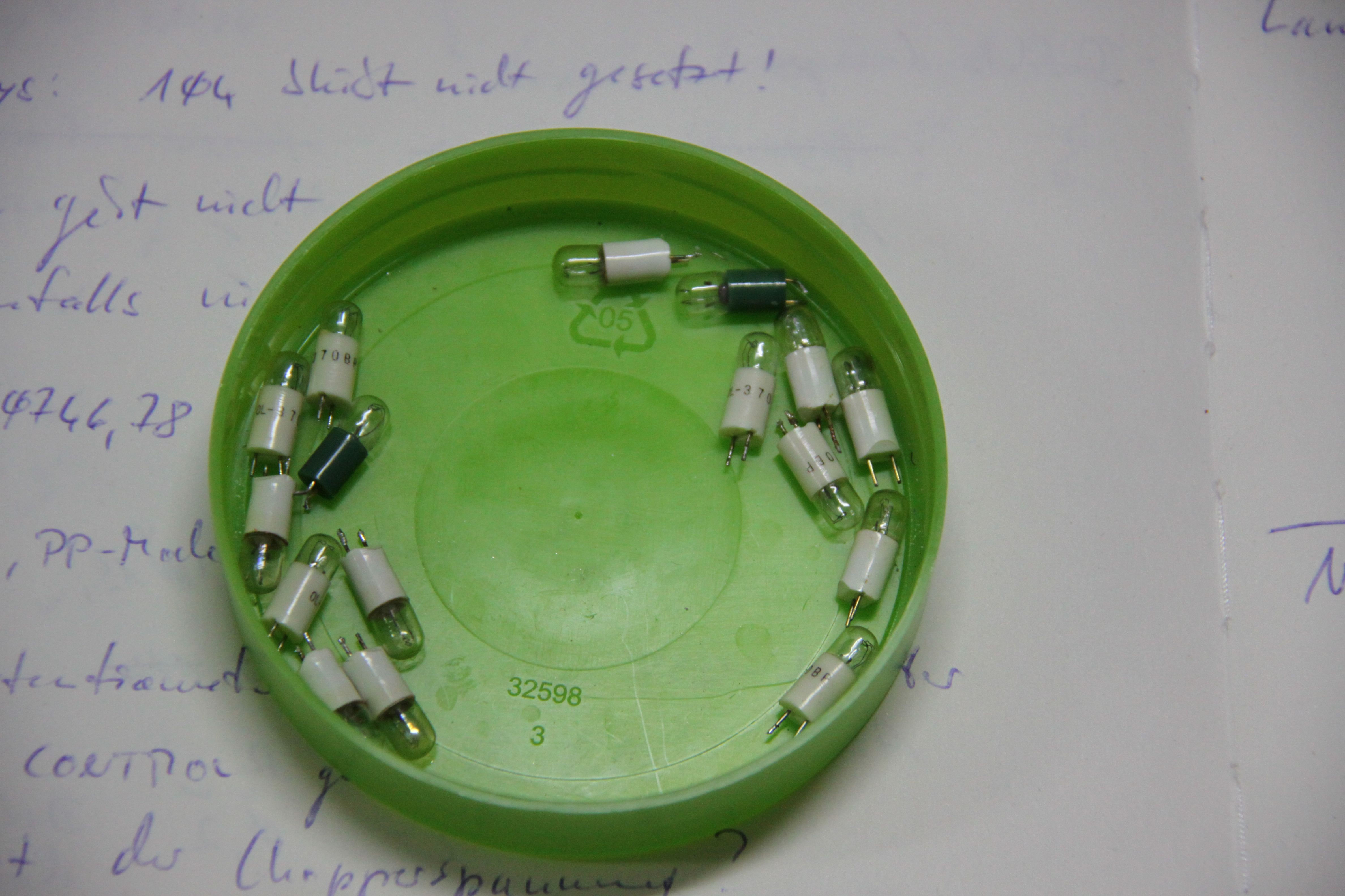
The last picture above also shows that some of the incandescent light bulbs used in the many switches were defective, so the next step was to replace these bulbs. Since there were no LEDs back in the late 1960s, incandescent light bulbs were used instead. The most prominent feature of many analog computers of this era is a projection display used to by the precision digital voltmeter and the component selection circuitry. These displays use up to twelve light bulbs for a single digit. Each bulb illuminates a small stencil, followed by a lens and a small screen. The picture on the left shows one such lamp module removed from the DVM display. Unfortunately, my stash of spare parts did not contain a suitable replacement for the burned out GE1909 bulbs, so I destroyed one of the defective lamps and built a small replacement part based on a yellow LED. The result is not very satisfactory as the focus of the LED is not exactly where it should be, so the symbol displayed by the projection setup is rather blurry. (I am still looking for GE1909 light bulbs!) |
|
|
|
|
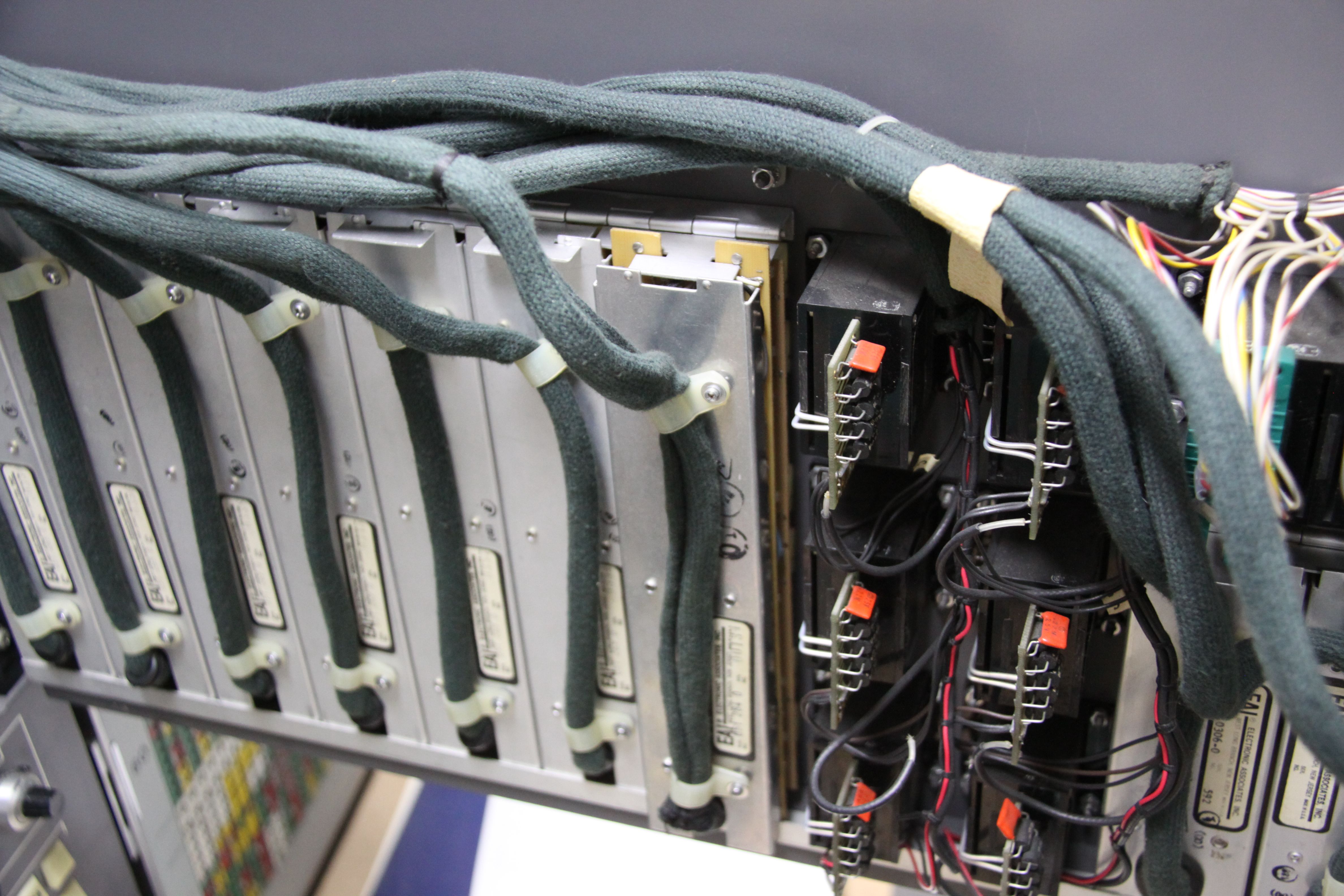
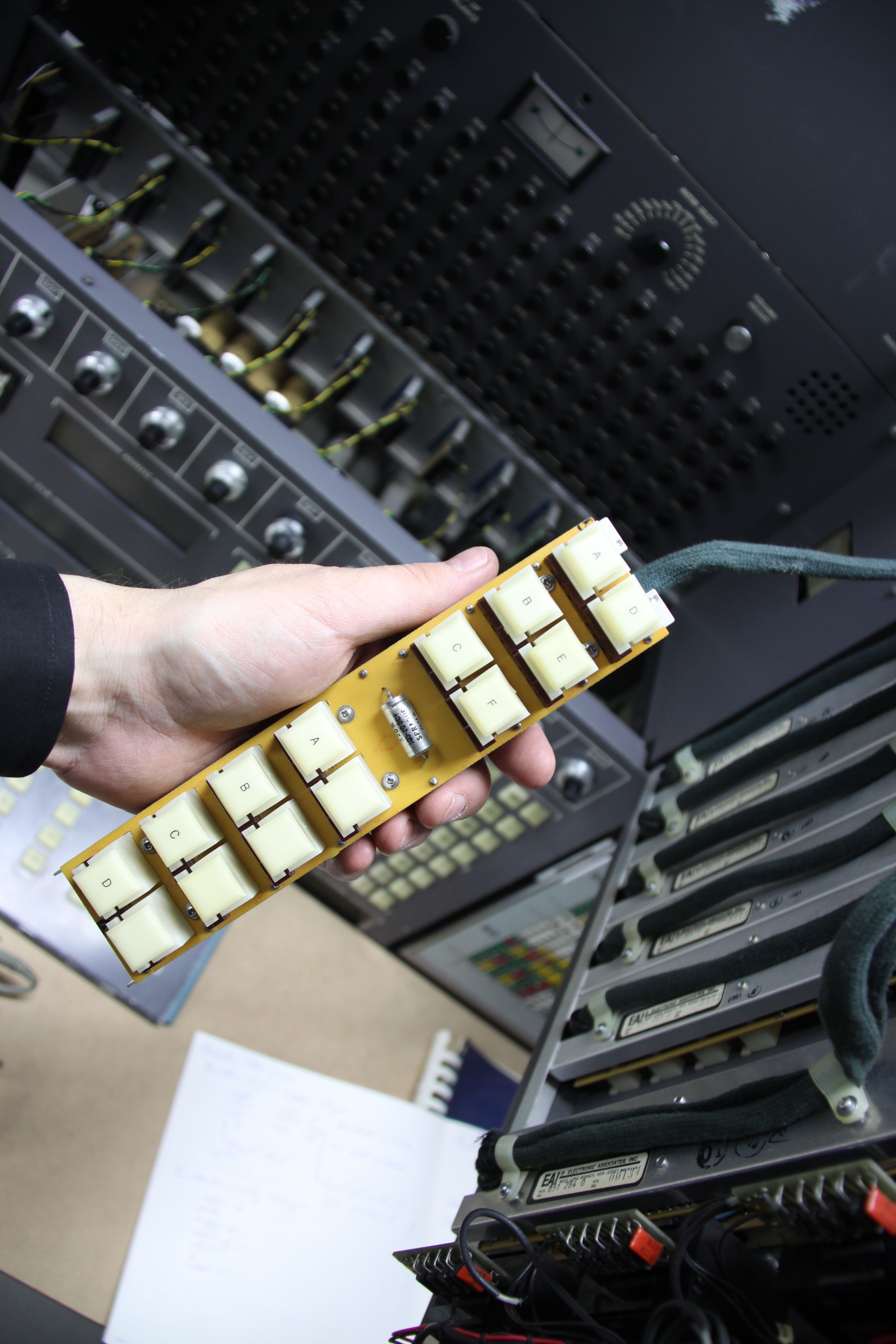
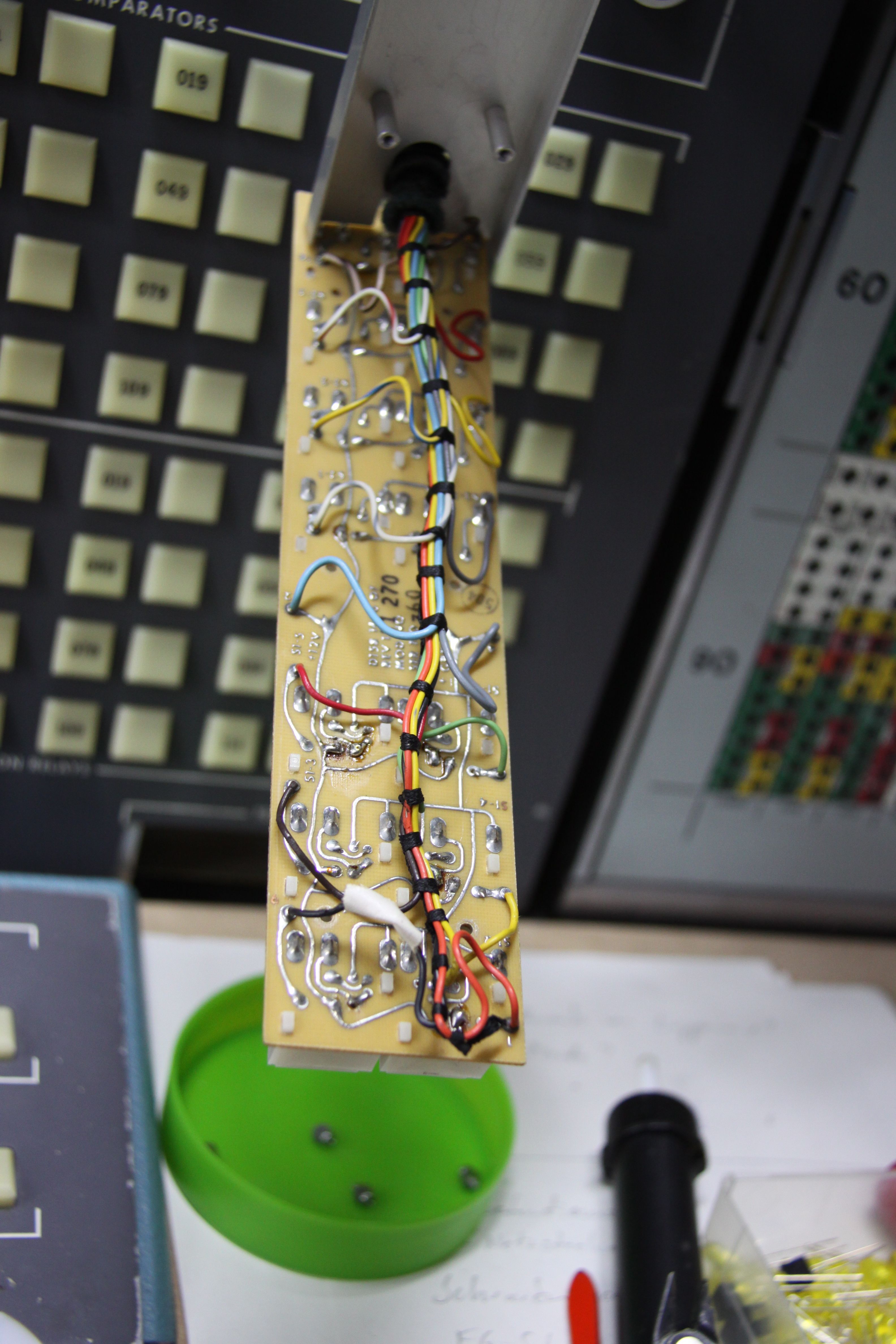
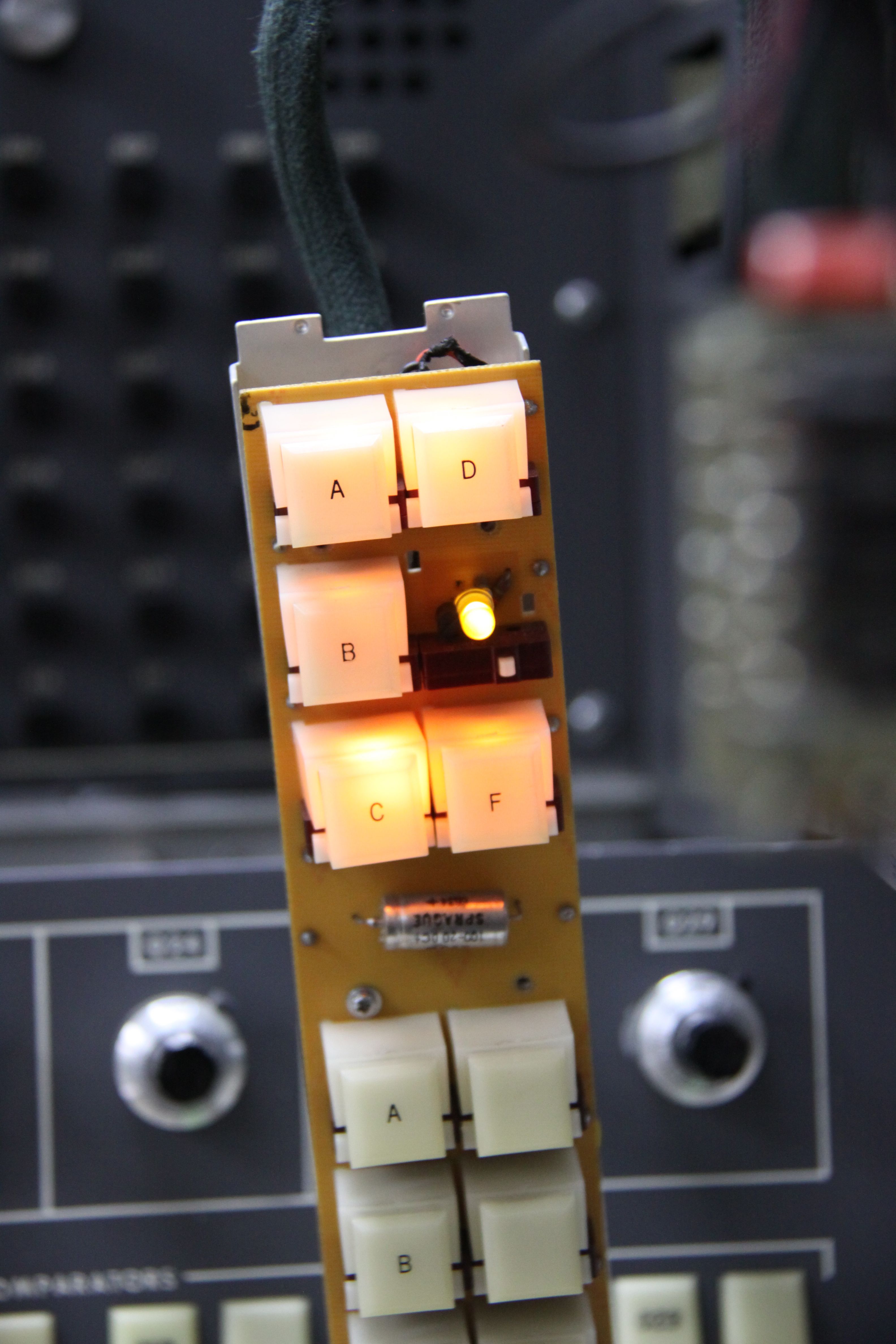
The remaining bulbs were much easier to fix, although this was an extremely time-consuming and nerve-wracking task. The picture on the left below shows the strips mounted behind the control panel of the computer. Each such strip holds two rows of manually operated pushbuttons, each equipped with a small incandescent light bulb. The picture in the middle shows one such strip while the picture on the right shows its soldering side. |
|
|
|
|
|
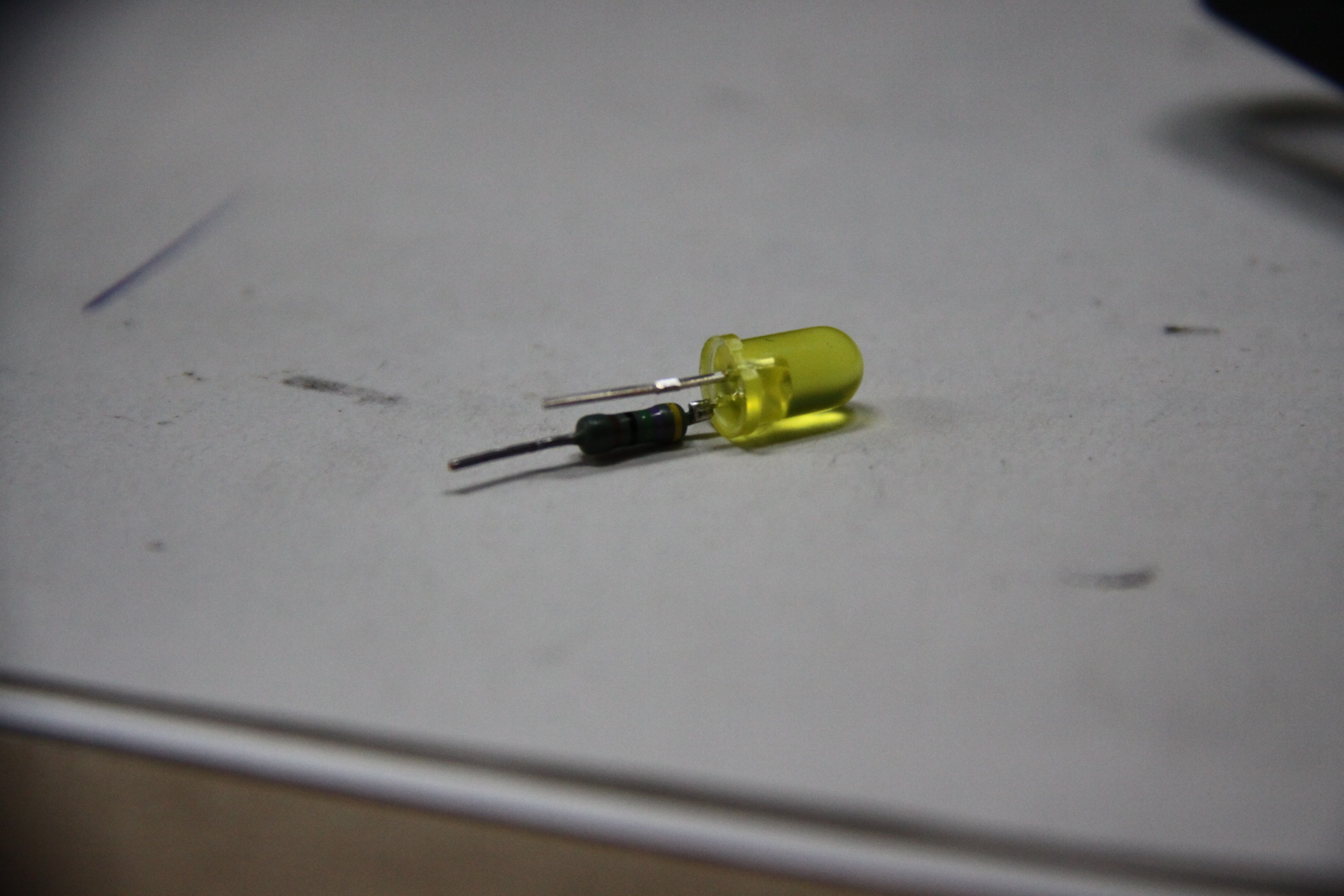
As I had no suitable replacement parts, I decided to use yellow LEDs with an appropriate series resistor. Since I always try to avoid modifying historic circuit bords, I soldered LEDs and resistors together as shown below left. The result, rather satisfying, is shown on the right. |
|
|
|
|
|
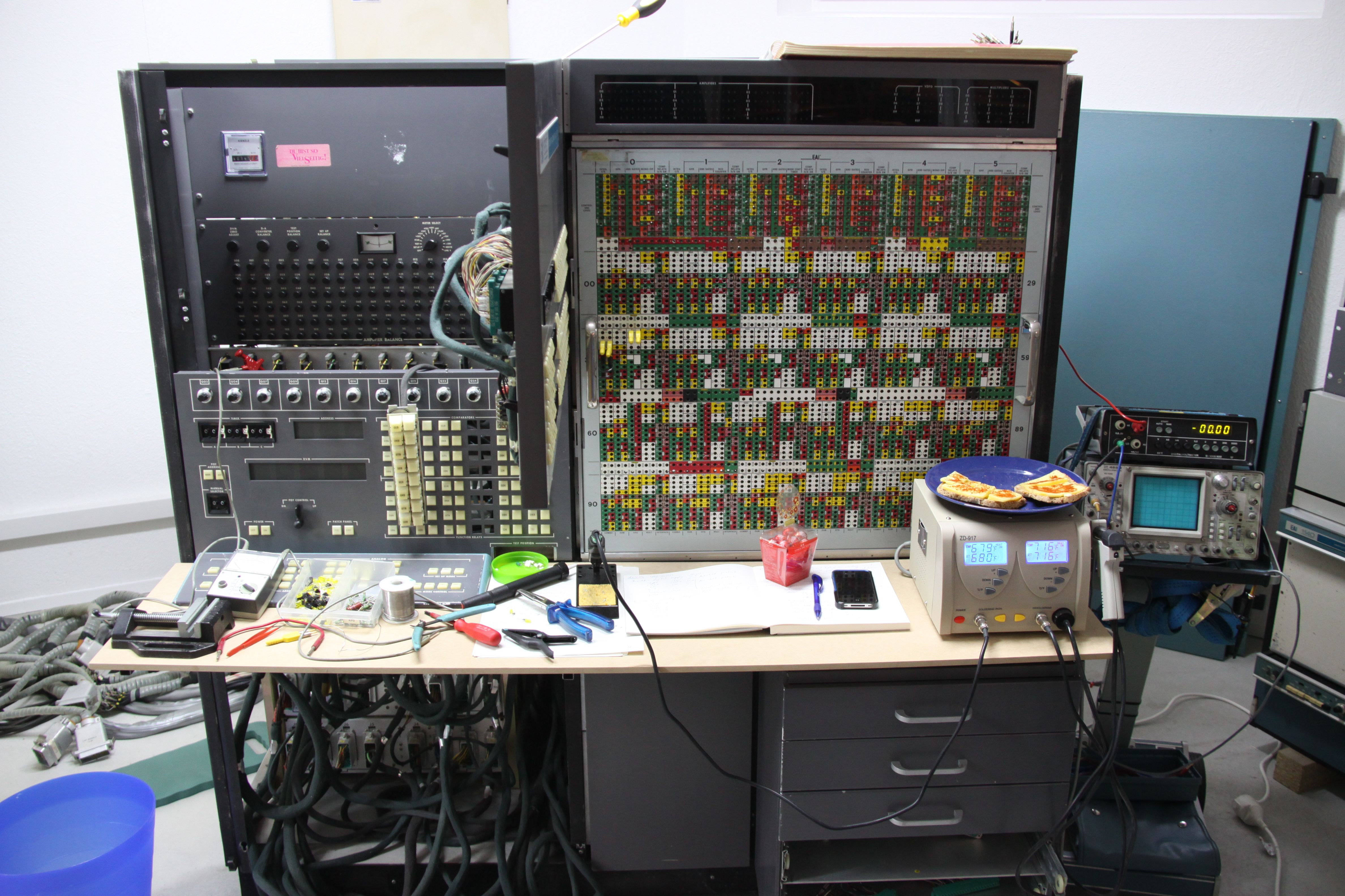
The picture below shows the machine during this part of the restauration. (Without Rikka's supply of cheese bread, chocolate eggs, etc. I would have starved during this phase! :-) )
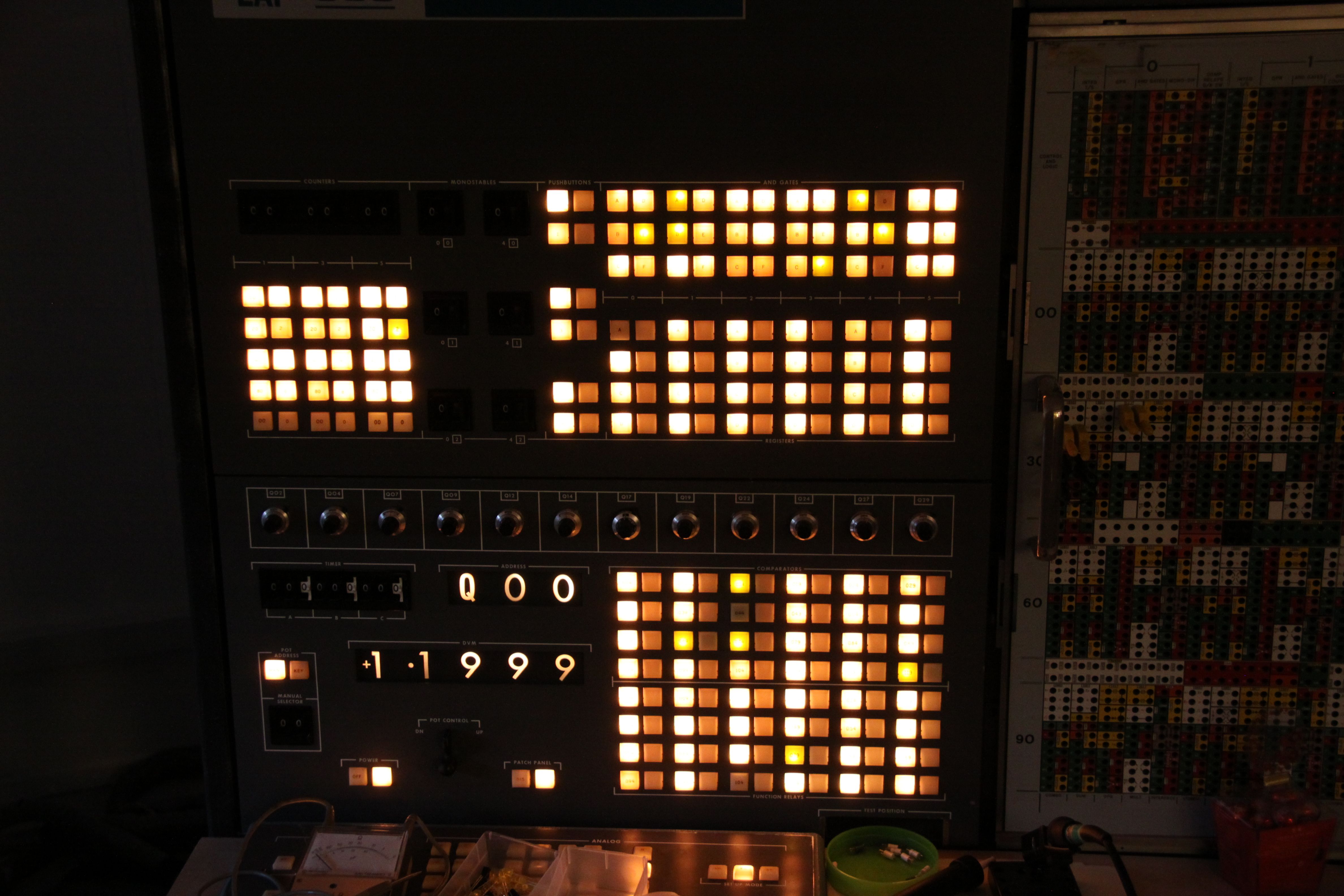
The next two pictures show the replaced bulbs and give an impression of the control panel in the dark (beautiful, isn't it?). |
|
|
|
|
|
Now it was time to install the 142 analog computing modules. My machine is extremely well equipped - the maximum number of modules is 150. The eight "missing" modules are multipliers which were most probably never installed in this particular system. Since some of the modules carry date stamps, it can be seen that the machine initially contained only about a third of these modules in 1967. The other modules were installed in 1969, 1972, and some in 1974. The picture below left shows one of these module prior to insertion into the card cage. All modules plug into a central backplane containing the necessary supply lines, various readout buses etc. The patchfield connectors are located on the front of the modules. This is a rather typical setup to keep parasitic capacitances low and patch cables short. The picture on the right shows the partially populated system (now weighing nearly one metric ton). |
|
|
|
|
|
Now, with the displays working (more or less - some additional light bulbs have died in the meantime :-( ), the power supplies in perfect shape, and the modules in place, it was time to setup a first program to get used to the machine and as a first mile-stone. I decided to program a simple Lorenz attractor. The picture below left shows the setup (requiring only a tiny fraction of the computing elements) while the picture on the right shows the machine with a small Tektronix oscilloscope used for output. |
|
|
|
|
|
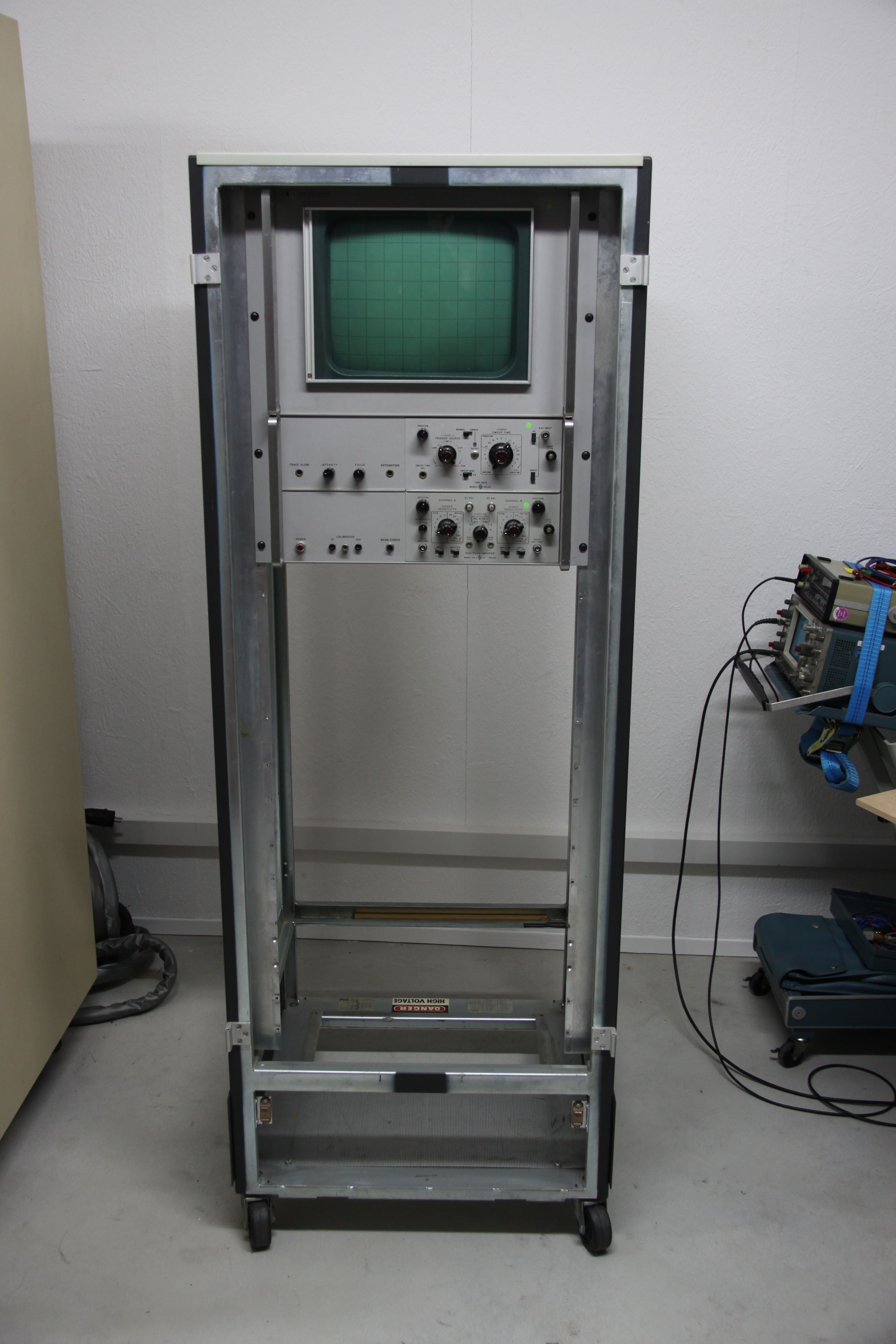
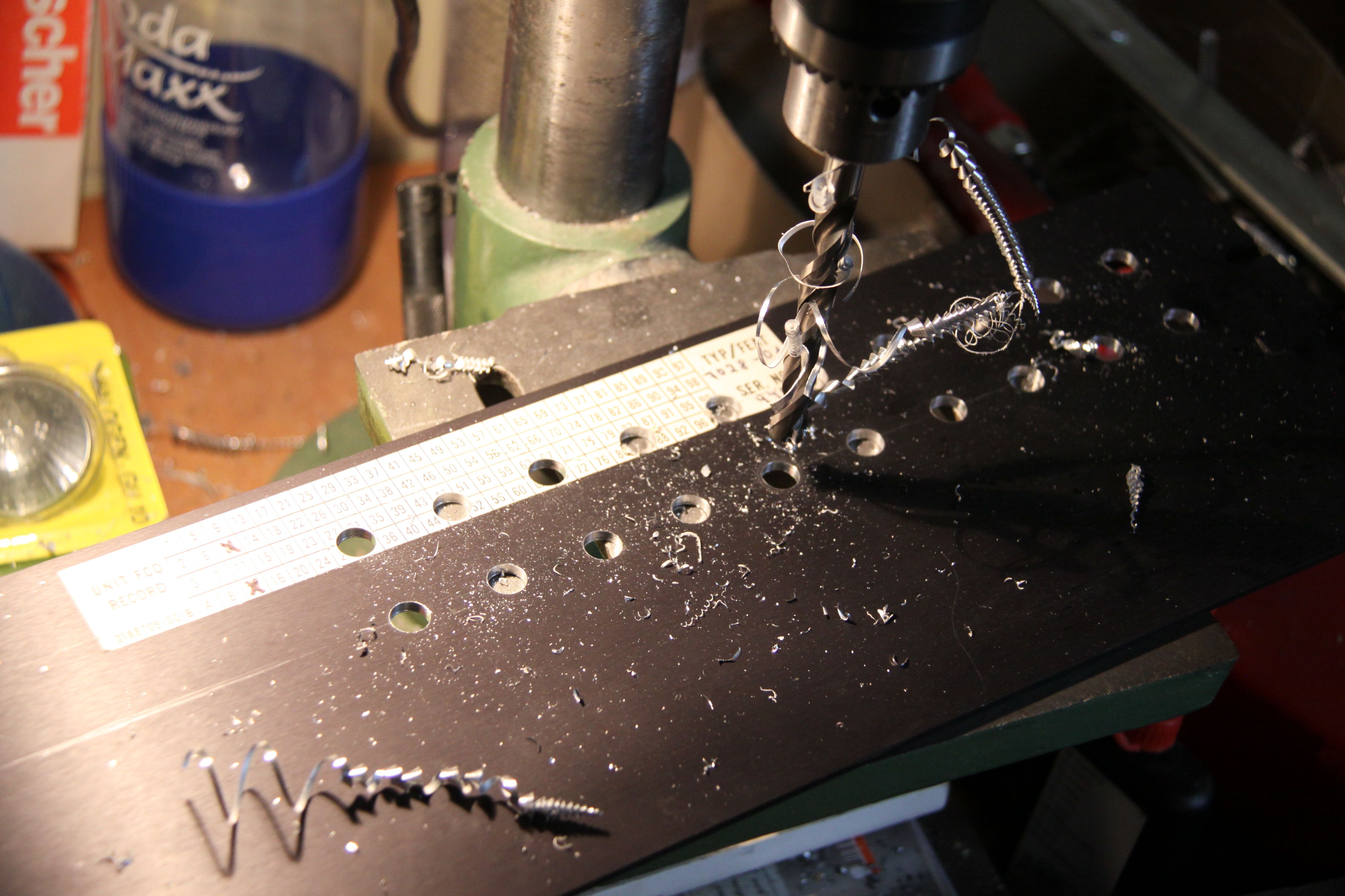
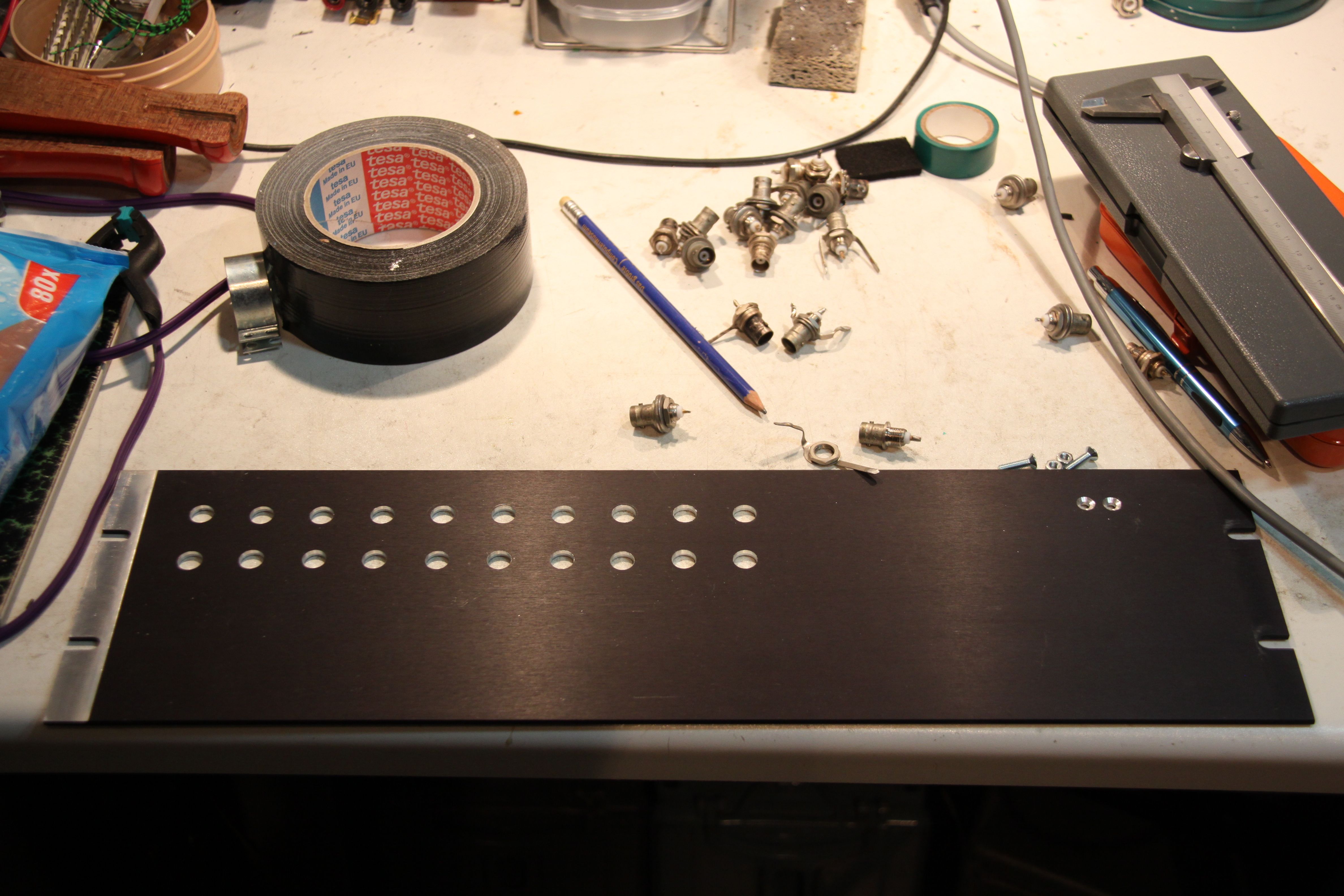
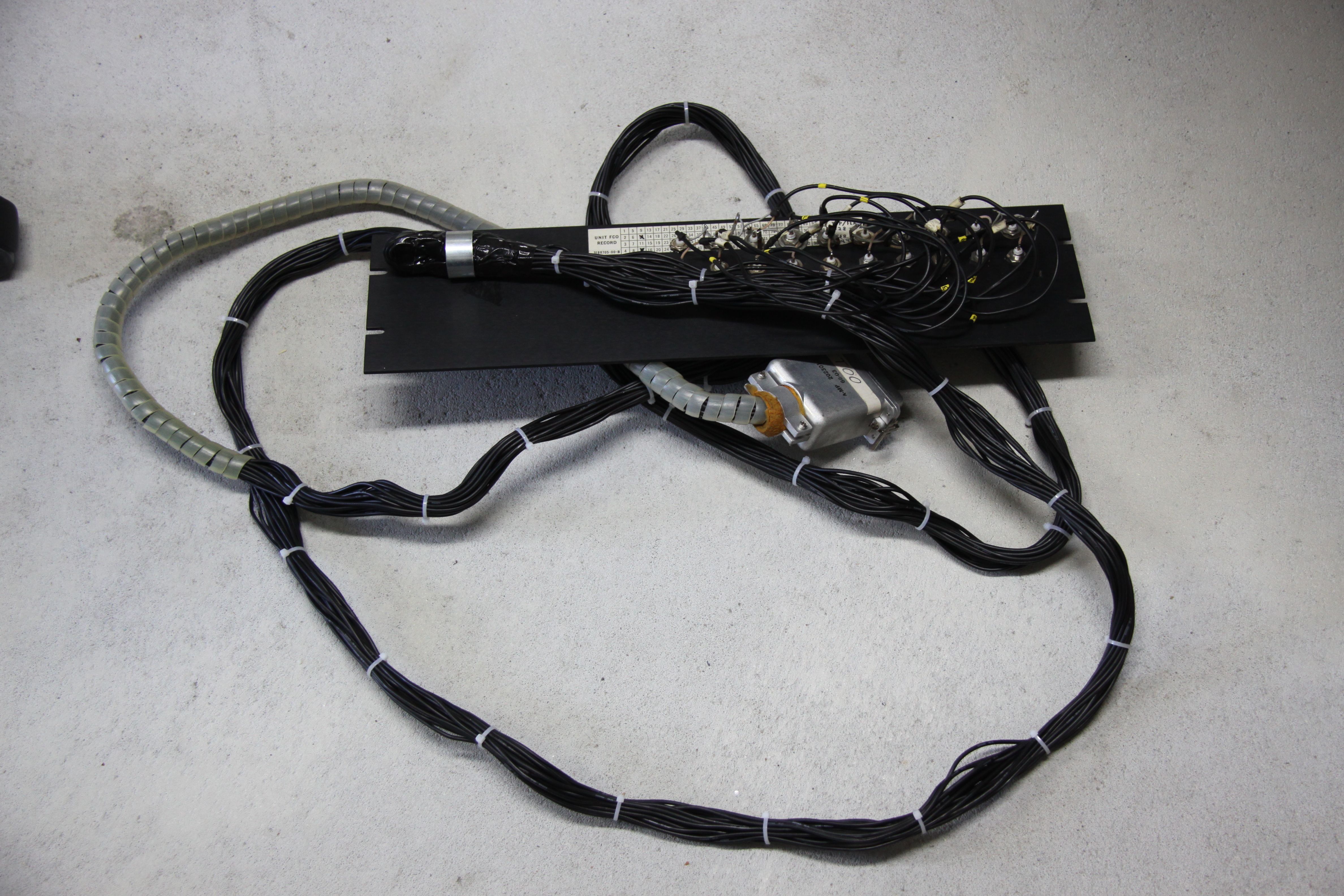
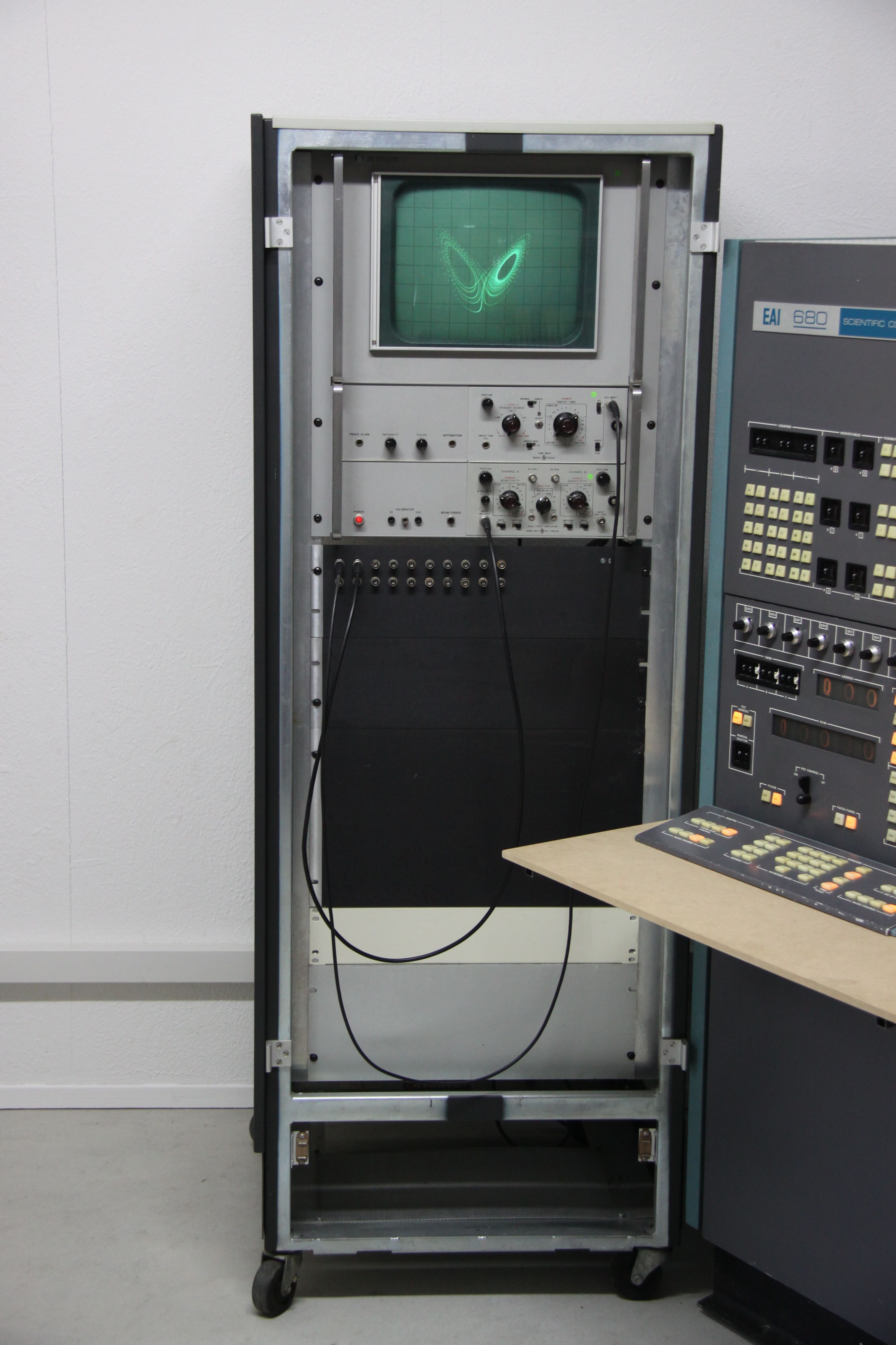
Now, that at least the major parts of the EAI 680 were working again (I still have to check each of its computing modules - some of which are definitely defective as their associated amplifiers are constantly overloaded) I remembered that I had a wonderful large-screen oscilloscope made by HP which would look beautiful with this machine. When I cleaned this instrument which I had saved many years ago from scrap, I found a small sticker and realized that it once belonged to this particular machine! What an incredible stroke of luck - they were separated tens of years ago and united in my house. :-) I mounted the oscillscope in an old 19 inch rack I had saved from scrap long ago as shown in the picture below left. Since I had (the pack rat again :-) ) suitable connectors for the so-called trunk lines of the EAI 680, I built some kind of a break-out panel to be installed beneath the oscilloscope. The twenty BNC jacks on this panel are connected to the first twenty trunk lines of the machine. The following pictures show the process of building this panel. |
|
|
|
|
|
|
|
|
The picture below shows the finished display rack with the oscilloscope on top, followed by the trunk line panel and a couple of blind panels for future expansions.
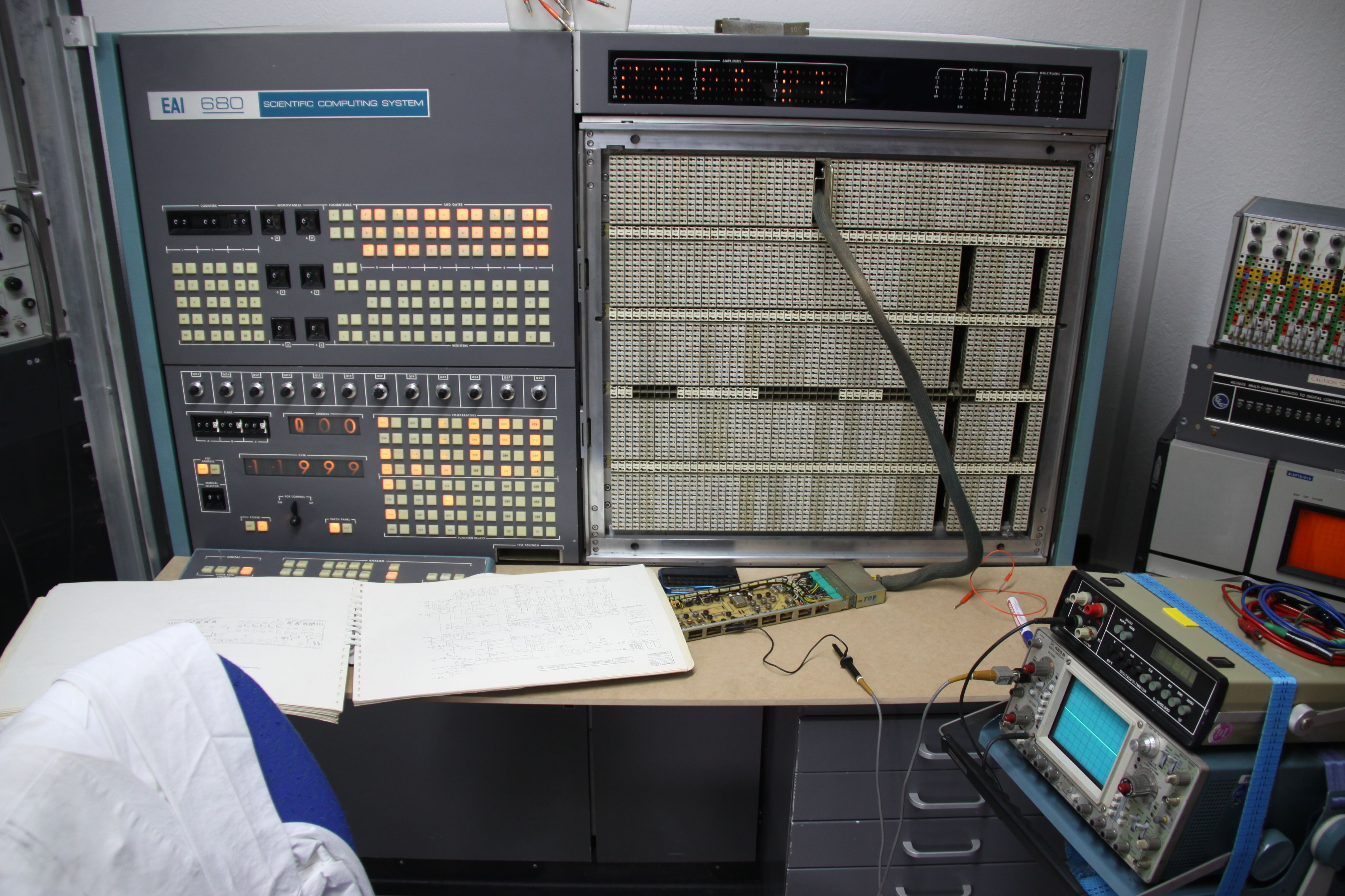
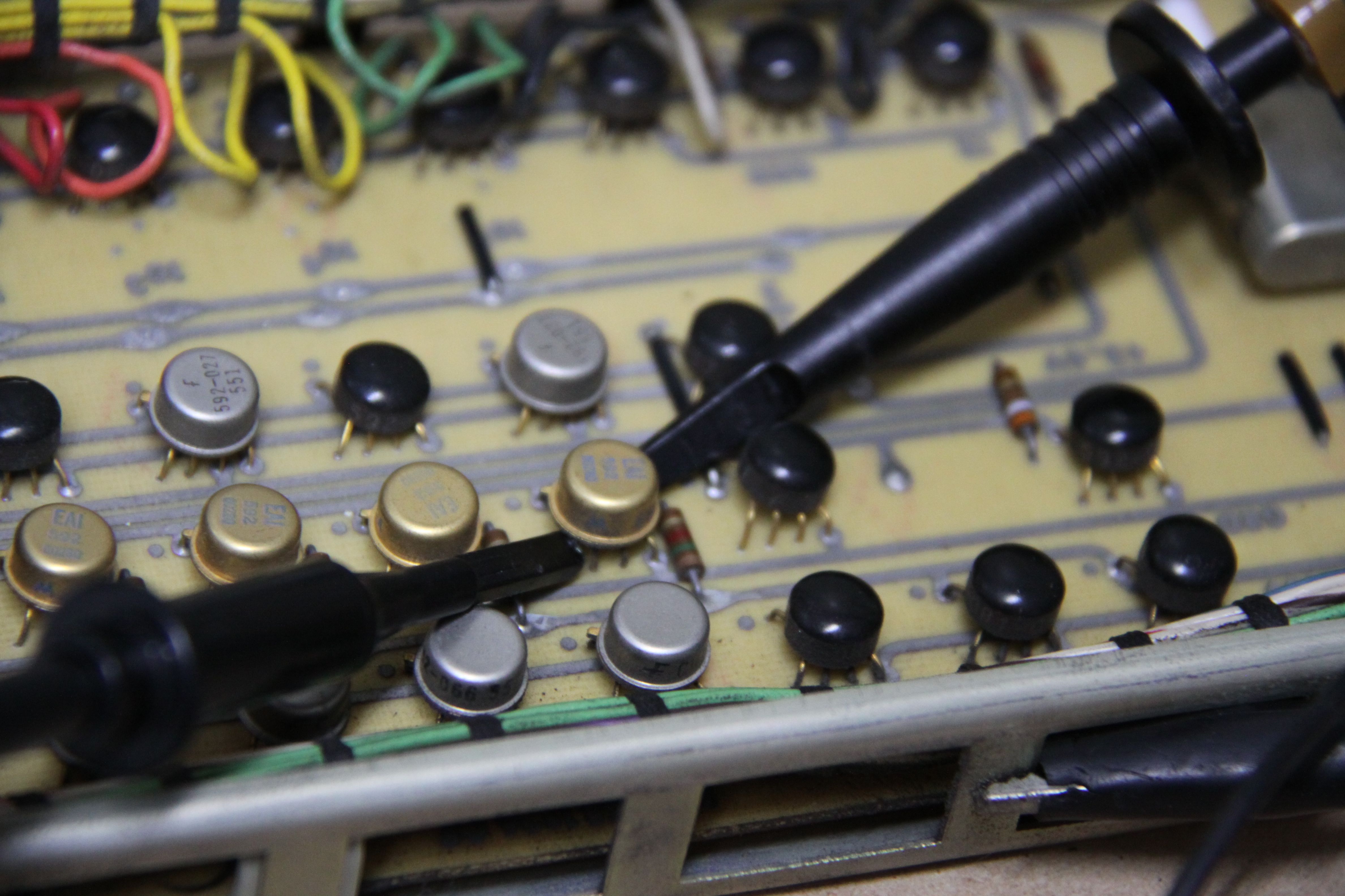
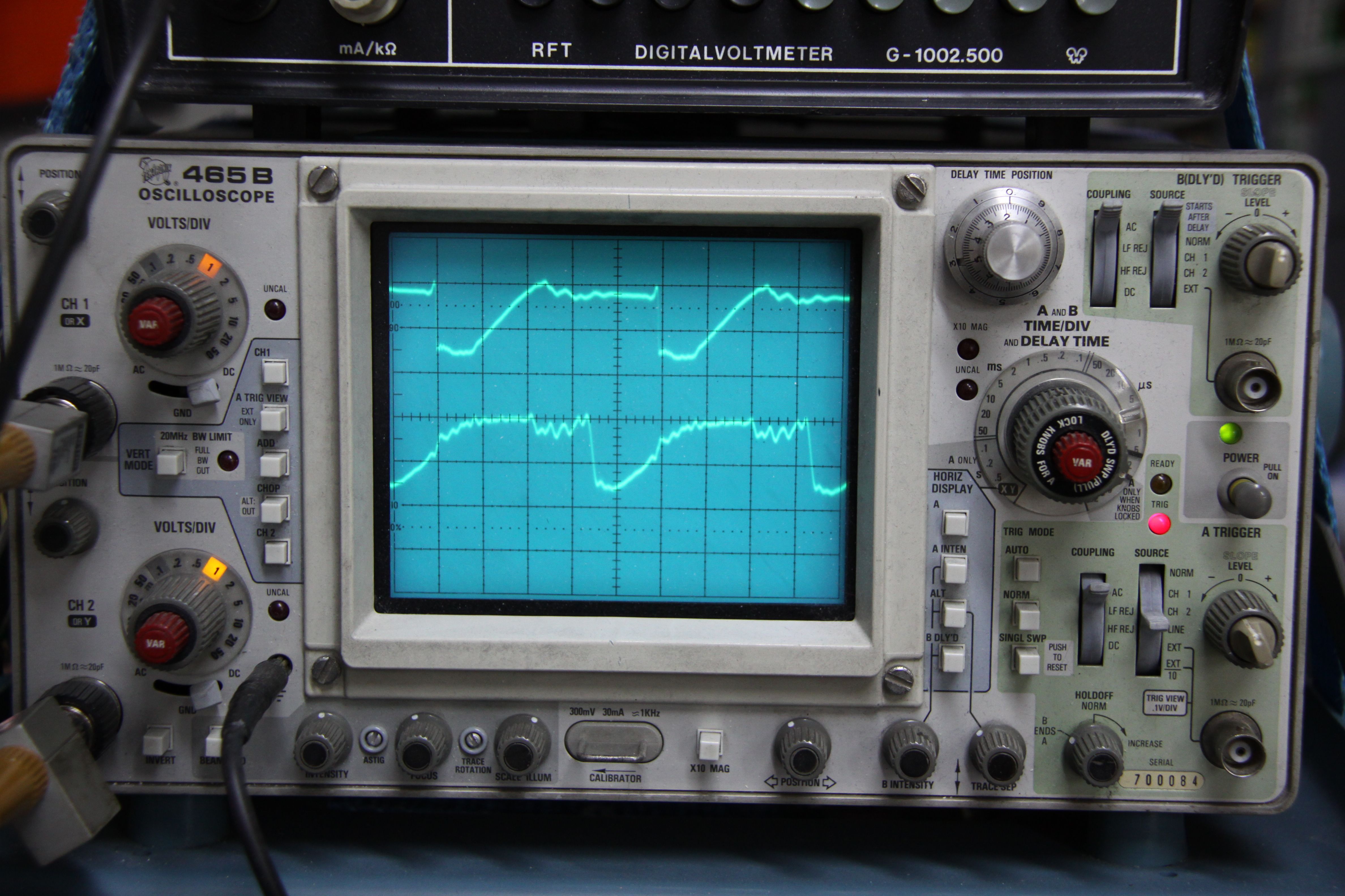
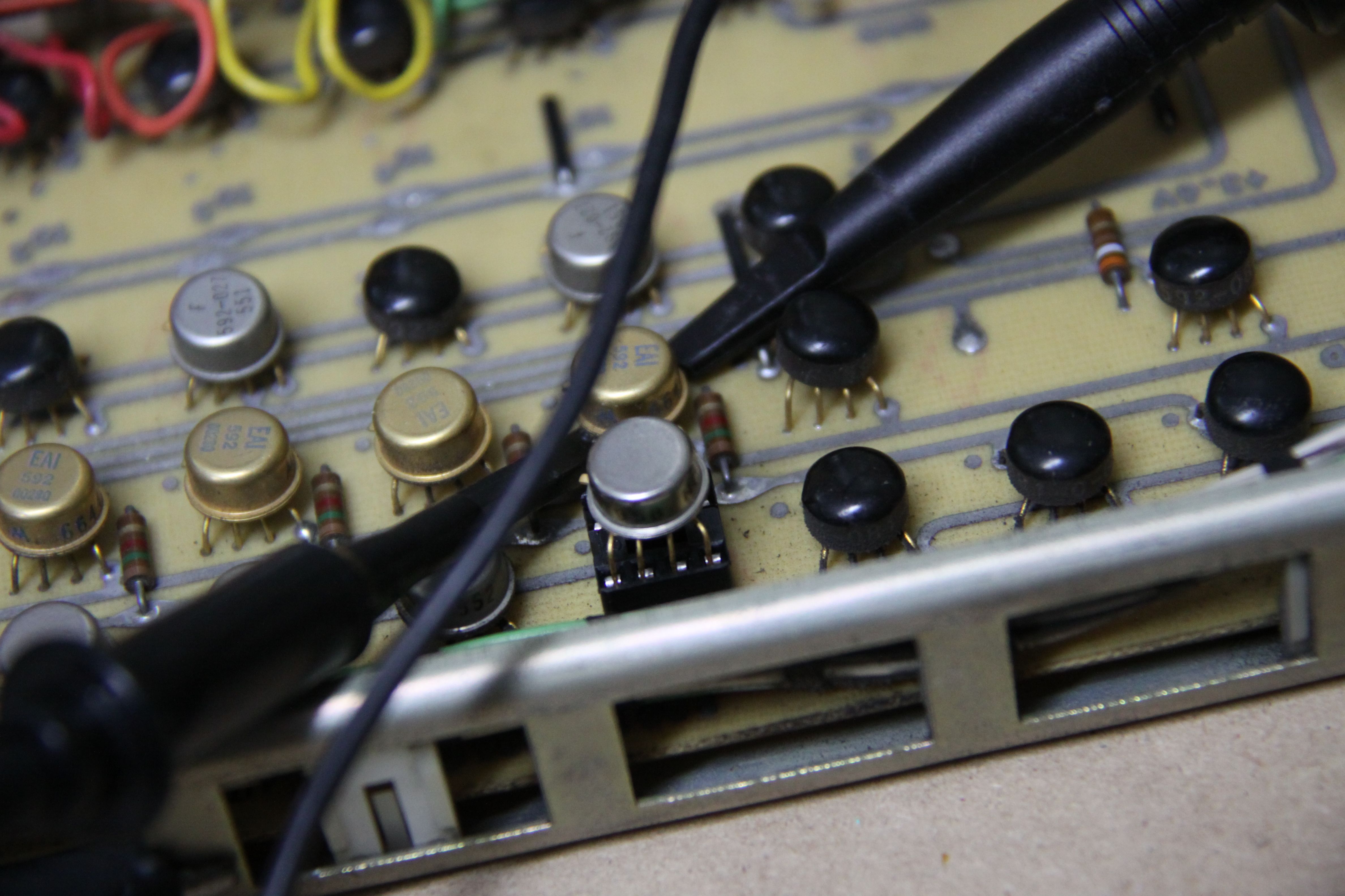
During the next couple of days I checked the various computing elements and made a list of problems which I need to fix in the near future. The most prominent problem was in the timing section: Only the highest clock rate and the single-step mode were operating normally. (Although this is an analog computer, it has a digital control unit which generates the necessary signals to setup, run, and halt the integrators etc. These control signales are derived from a quartz controlled central clock.) It turned out that the first divide-by-ten stage was inoperable. Fortunately (the pack rat yet again :-) ) I have a suitable extender board for debugging the digital control boards of an EAI 680. (The analog circuit boards can be plugged into a dedicated port right next to the manual control panel in the desk for debugging purposes, but the digital circuit boards require different signals.) The following four pictures show the setup during debugging, the logic chips used by EAI (rather unusal from today's perspective in their metal can enclosures), the output signals of the divide-by-2 and divide-by-8 stages of the first divider (which are obviously faulty), and the replacement part I fitted in a socket. (It is next to unbelievable, but I had a NOS replacement part in my collection. :-) Otherwise this bug would have been more difficult to fix since the logic levels used in this machine are quite incompatible with TTL circuitry.) |
|
|
|
|
|
|
|
|
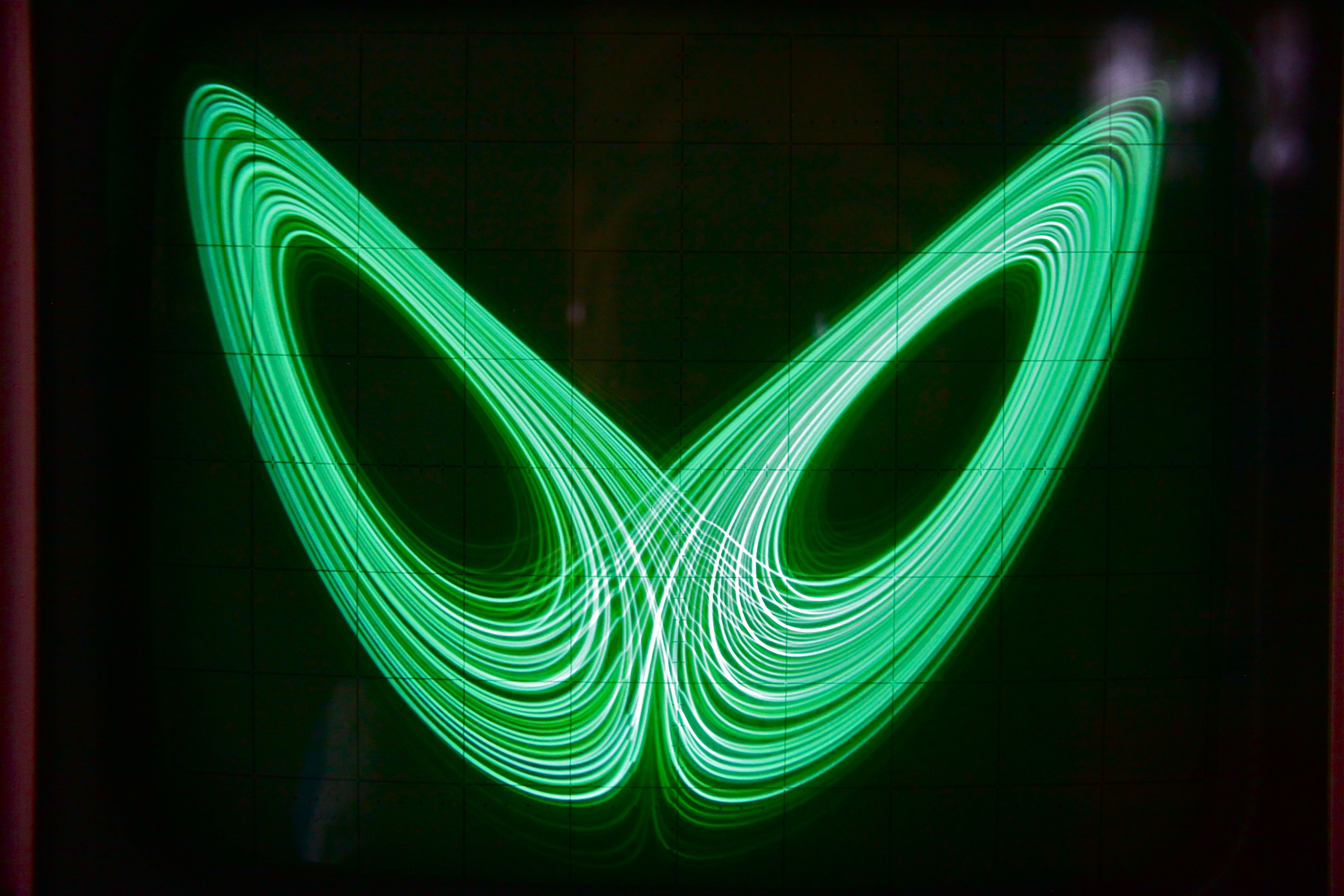
One final picture (this report will continue, but the next update will take some time) of the Lorenz attractor generated on the EAI after fixing two minor problems in the HP oscilloscope:
|
|
|
01-MAY-2014, ulmann@analogmuseum.org |
|