Donner 3000
|
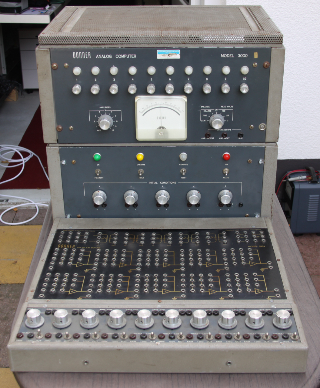
Some time ago I bought the remains of two Donner 3000 analog computers from 1958 for way too much money (honestly, yes, but on the other hand - is there anything better one can do with money than buying old helpless computers and repair them? :-) ). Apart from being incredibly dirty, both were missing one of the main transformers and both had been modified in the past (not too expertly - isolating lines carrying +570 V with adhesive paper tape does not sound to clever to me), so they sat on a shelf for quite a while (about two years) until I started looking deeper into them. The following is the description of a work in progress - as of now, January 2016, only one power supply is working again. The next module to be repaired will by the 10-amplifier drawer, followed by a patch panel and a potentiometer strip. These modules combined form a basic Donner 3000 analog computer as shown above. |
|
|
|
|
|
|
|
|
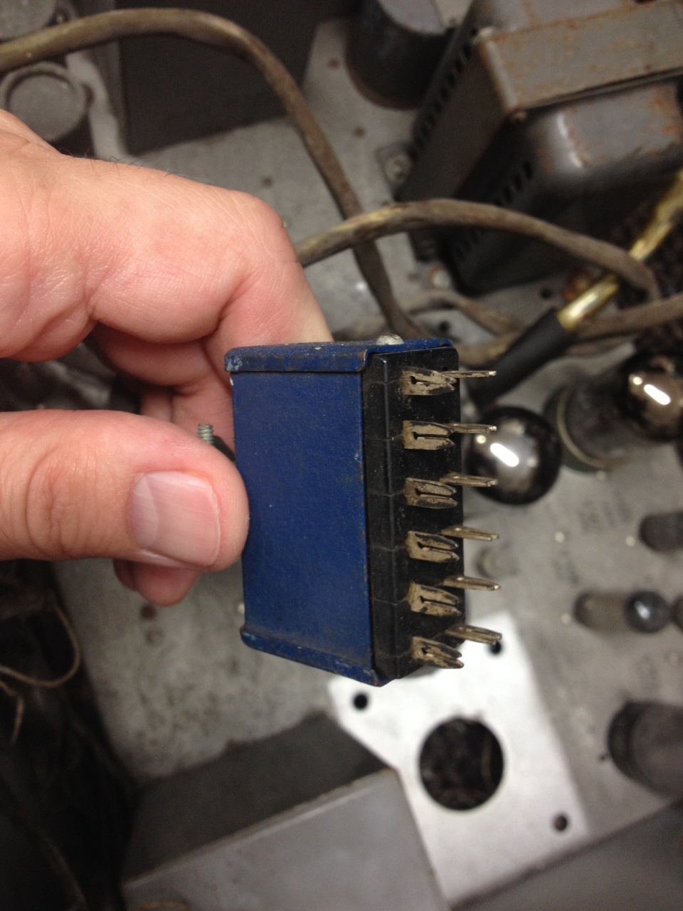
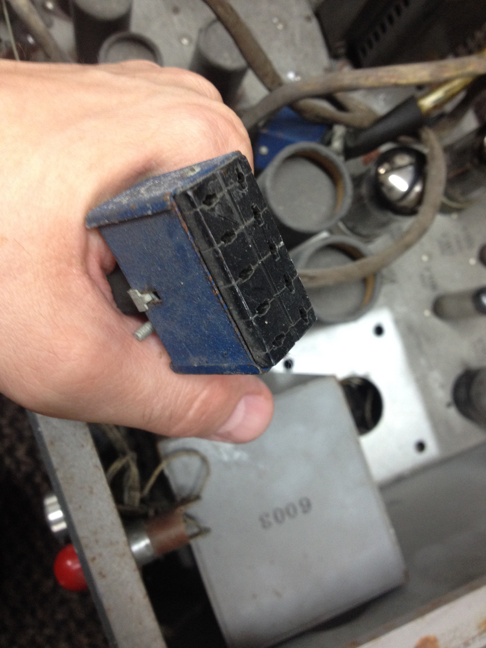
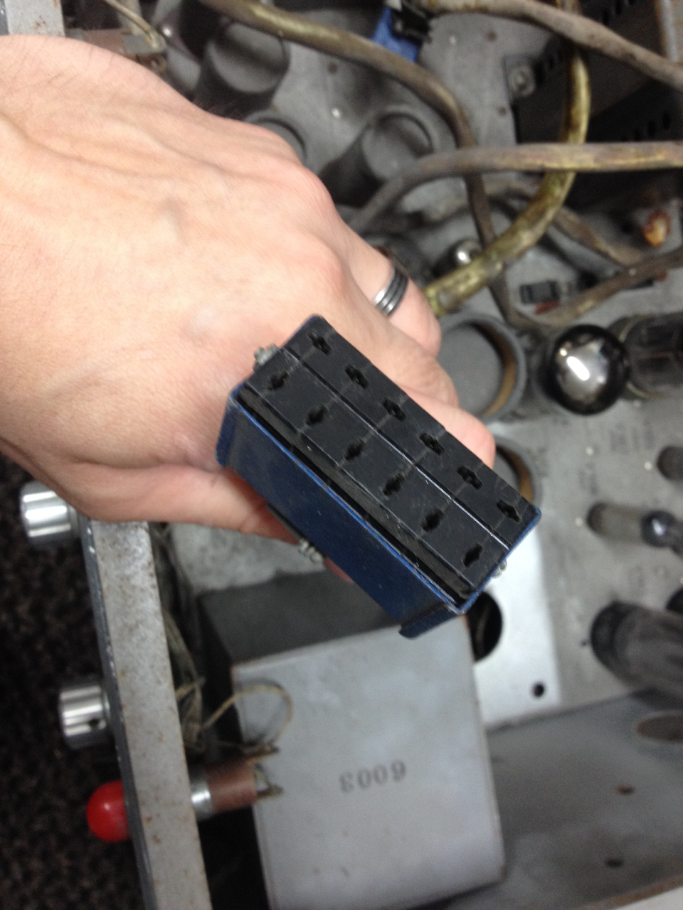
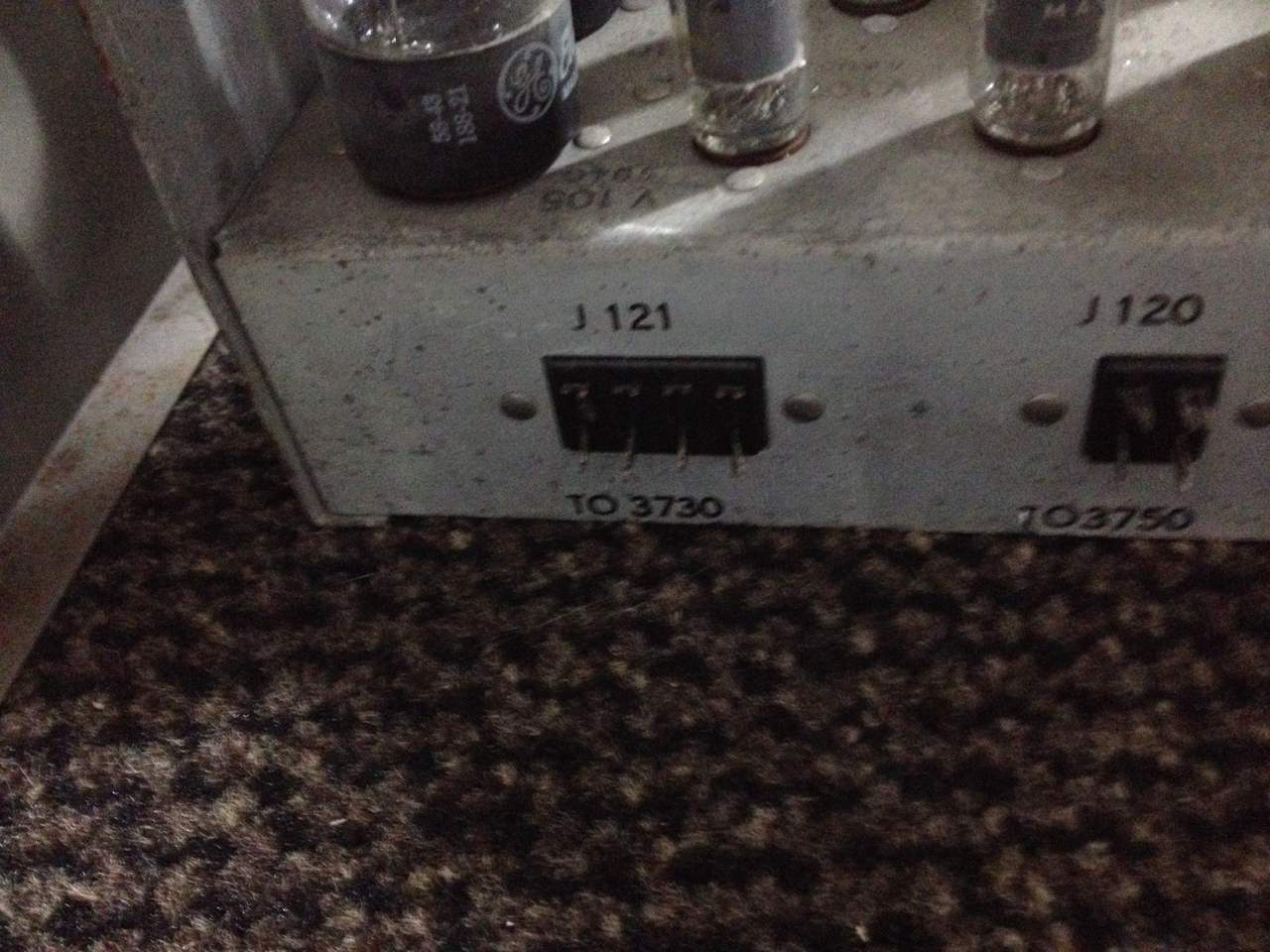
A plea just at the beginning: The Donner 3000 uses connectors like those shown above - unfortunately some have been cut off by some previous owner while other have broken contacts, so I am looking for connectors (plugs and jacks) like these. If you have something like this to spare, please let me know: ulmann@analogmuseum.org |
|
|
|
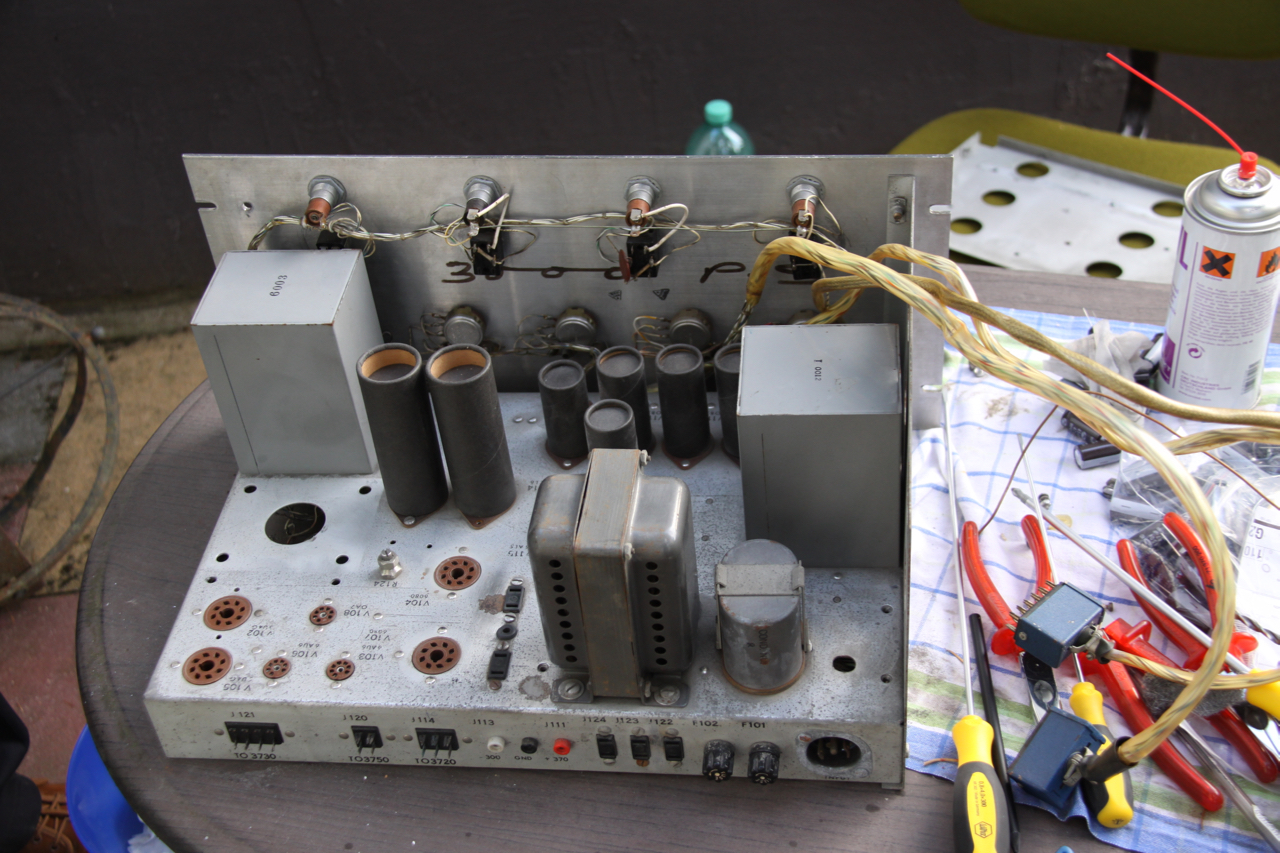
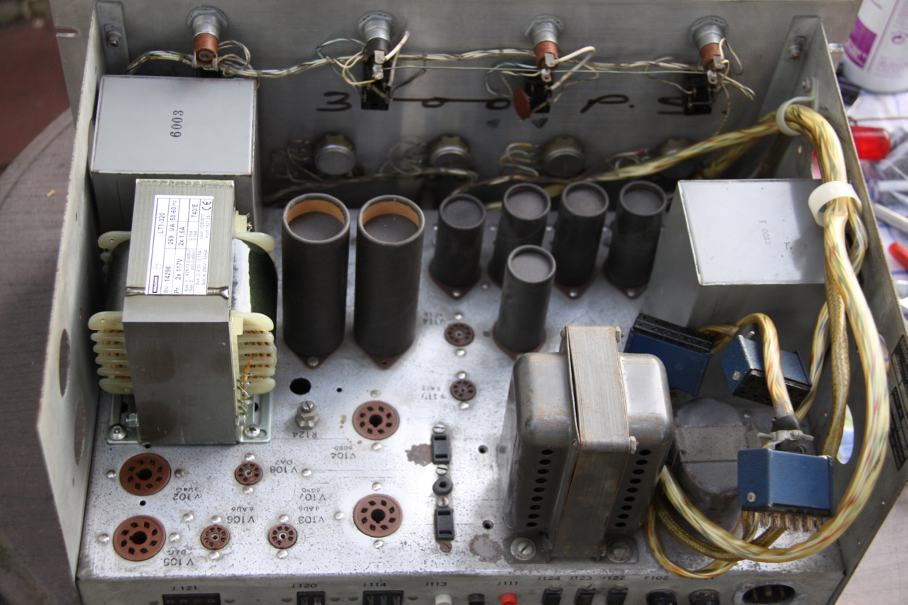
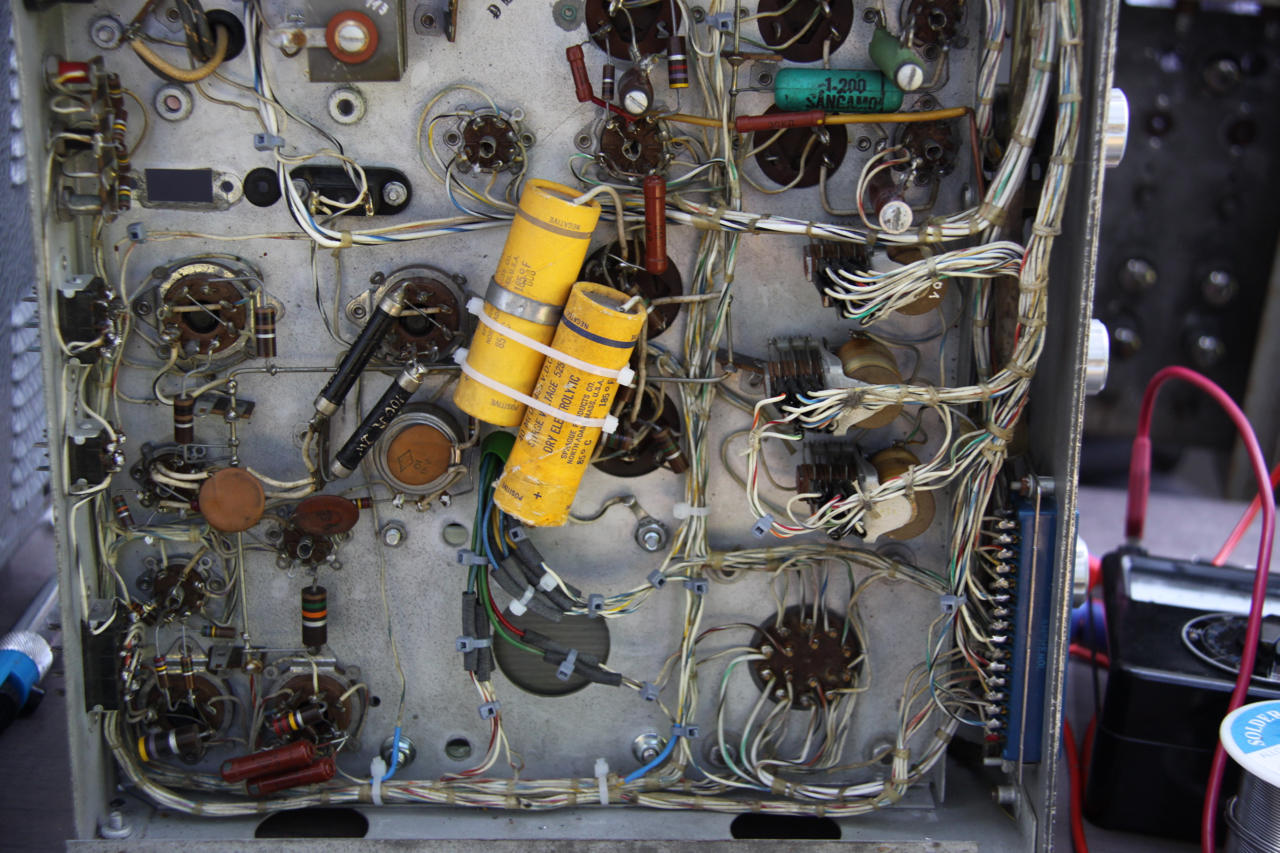
The picture on the left shows the power supply after some initial cleaning. Clearly visible is the missing transformer on the left. Examining the bottom of the supply shows that some has done quite some modifications to the unit. Closer inspection showed that some secondary windings of the transformer used to generate the initial-condition voltages for integrators have been rewired to partially replace the missing transformer. I wonder if this transformer may have failed in both units since it is missing from both and both show quite similar changes to their circuitry (the schematic for this unit can be found in the library section). Note the seven Selenium rectifiers visible on the bottom lower left - these generate the initial-condition voltages which are then fed to simple potentiometer voltage-dividers. The green and white mantled cable bundles are not part of the original circuit and have been removed during the restoration. |
|
|
|
|
Finding an original replacement for the missing transformer turned out to be impossible as it needs to have 425-18-0-425 V, 400-0-400 V, 6.3 V, and 250 V on its primary side (about 270 VA all in all). So I had one custom-made (about 120 EUR/piece) by Walcher, and I have to say that I am really pleased with the result. I am glad that my friend Bernd Johann participated in the repair as I hate working on vacuum tube circuitry alone. :-} Although it does not fit with regard to style, it is electrically perfect and has the right size to fit into the empty space of the original transformer (I only had to drill four new mounting holes which is a pity but was unavoidable). |
|
|
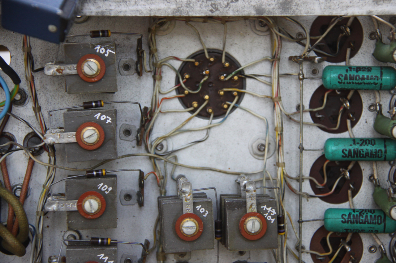
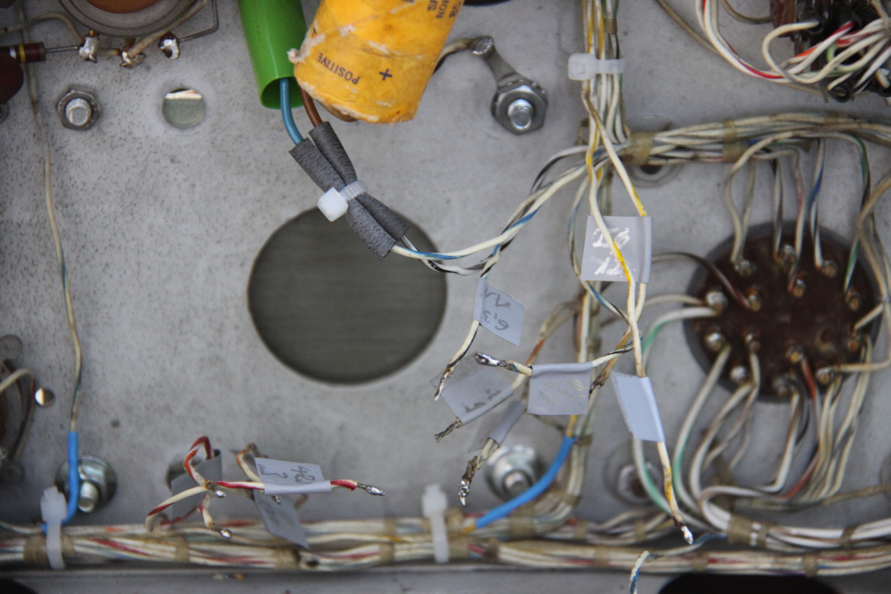
The picture below left shows part of the initial-condition circuitry after rewiring it according to the schematics. Ony secondary winding of the transformer had been sacrificed to replace the 250 V output of the missing transformer (the remaining missing voltages have most probably been fed externally to the computer as there was retrofitted connector on the back which was in turn connected to the unregulated lines of the regulator circuits - this has been removed as well). The picture below right shows my labeling of the dangling wires which once were connected to the now missing transformer. It took quite some time too beep them out even with the aid of the schematics. |
|
|
|
|
|
The next step was a basic safety test with respect to ground impedance and leakage, shown in the picture below left. Leakage current turned out to be 0.15 mA, so the next step was to reconnect the dangling wired to the secondary windings of the new transformer which is shown in the picture on the right. (Believe it or not but all electrolytic capacitors are still OK, no excessive leakage and basically all still more or less in spec - I am still amazed...) |
|
|
|
|
|
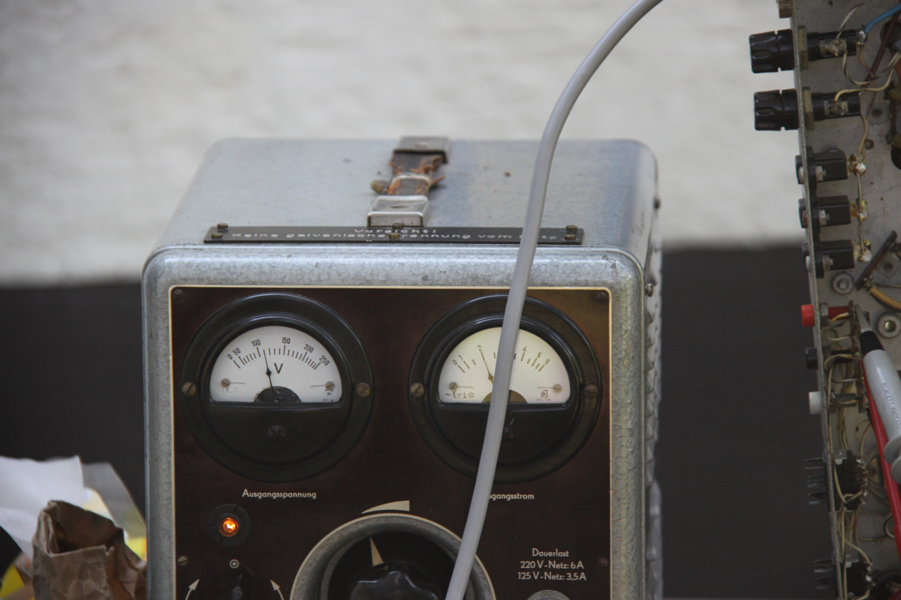
When the rewiring was completed time had come for a more thorough test shown below. Amazingly the power supply worked right out of the box! All voltages were still within spec - shown below left is the measurement of the +370 V line (that's not the highest voltage to be found in this power supply!). Running without any load connected, the power supply draws about 2 A at 110 V as can be seen below right. |
|
|
|
|
|
|
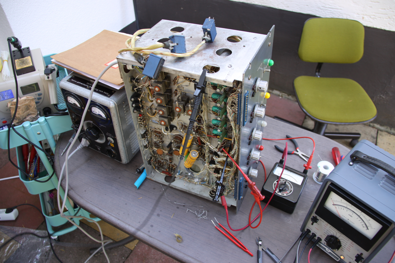
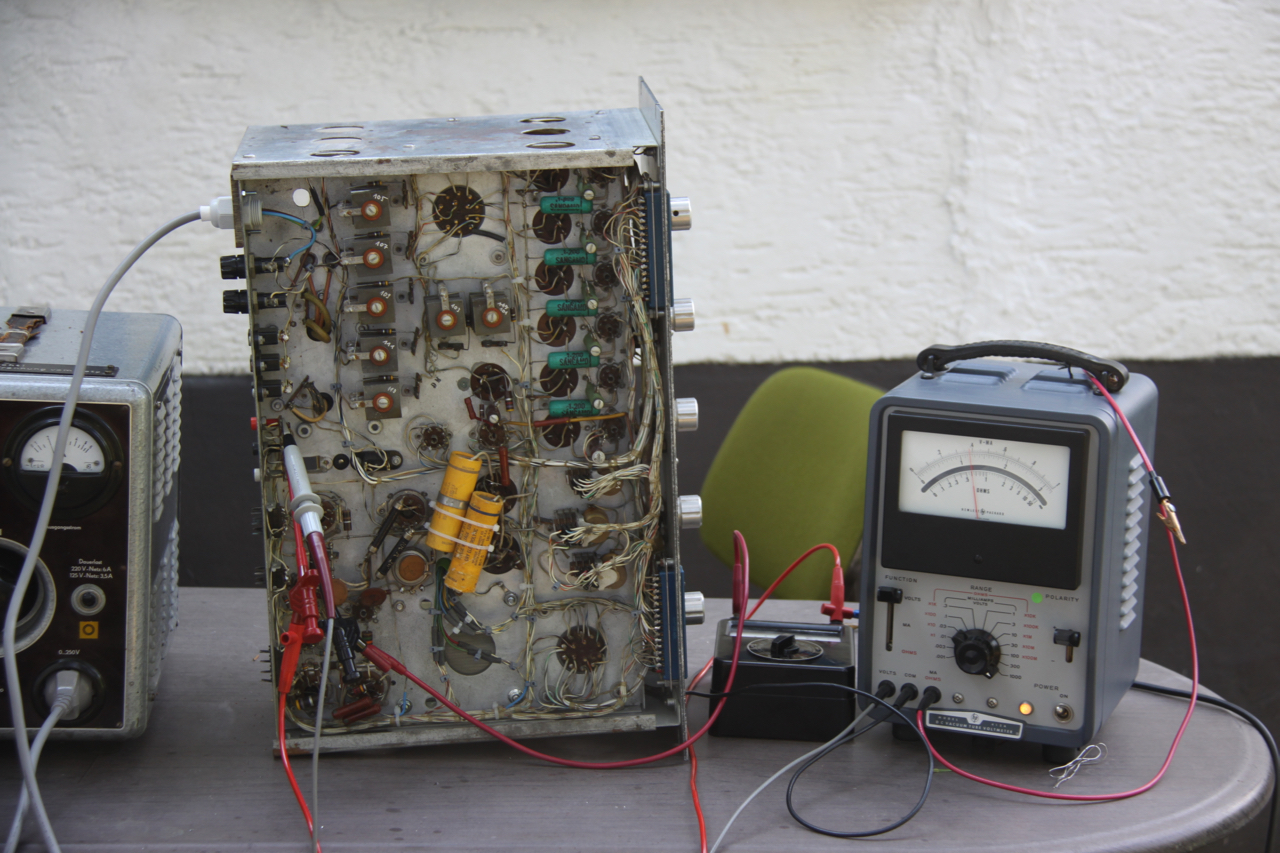
The picture on the left shows the power supply (below) with the amplifier drawer mounted on top (I still think that the connectors are a bit flimsy for 370 and over 500 V but obviously it worked back then so it should work now, too :-) ). As of now there the +370 V line is missing in the amplifier drawer - there are still changes to the circuitry which I have not yet found, so stay tuned for updates to come in the future. I am confident that this beauty will be up and running again soon (more or less :-) ). |
|
One year later... |
|
|
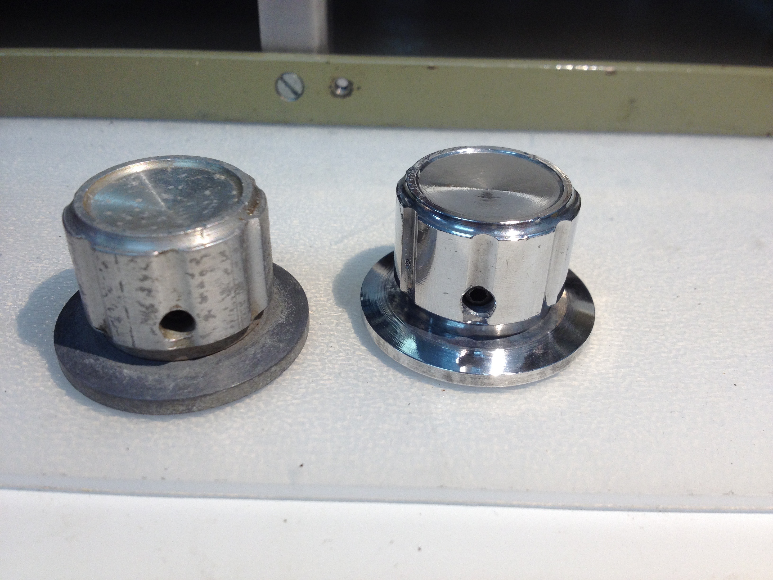
It took a bit more than a year before my friend Bernd Johann and I met again to continue work on the Donner 3000. In the meantime my friend Joachim Wagner did a terrific job polishing the knobs of the machine. On the left is a knob in its original state, on the right one after Joachim polished it! When we temporarily stopped our restauration efforts last year, the power supply was more or less operating satisfactorily but the +370 V voltage for the operational amplifiers was missing (and with that the +520 V, too which is derived from stacking a regulated +150 V source on top of the +370 V rail). After some head-scratching and reverse engineering it turned out that the lower end of the +150 V was correctly connected to the +370 V pin on the power supply jack connected to the amplifier. Interestingly, the crucial connection between this line and the actual +370 V output of the power supply was just missing. I assume that it was removed by the previous owners who circumvented the (presumably defective) main transformer - maybe they fed this voltage from an external power supply. |
|
|
|
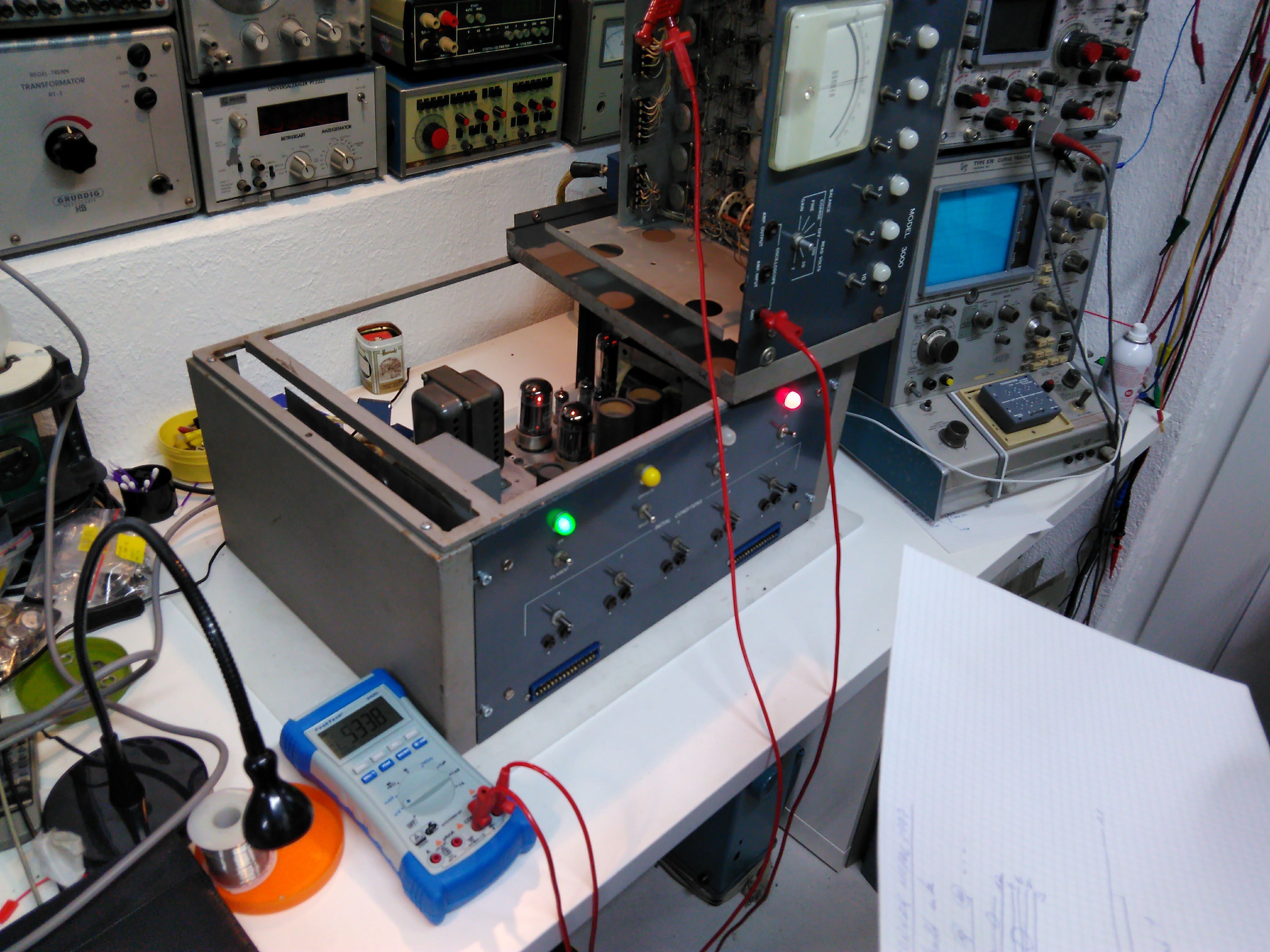
After we added a wire connecting the lower end of the +150 V supply and the +370 V rail all voltages were now correct so that we could have a look at the amplifier chassis. The picture on the left shows the working power supply with the amplifier chassis connected to it during a short test run. The voltages turned out to be a bit too high, so the stabilized -300 V voltage was adjusted accordingly, bringing the other voltages within range, too. |
|
This is a good place to talk a bit about the power supply - the picture below is part one of the corresponding schematic:
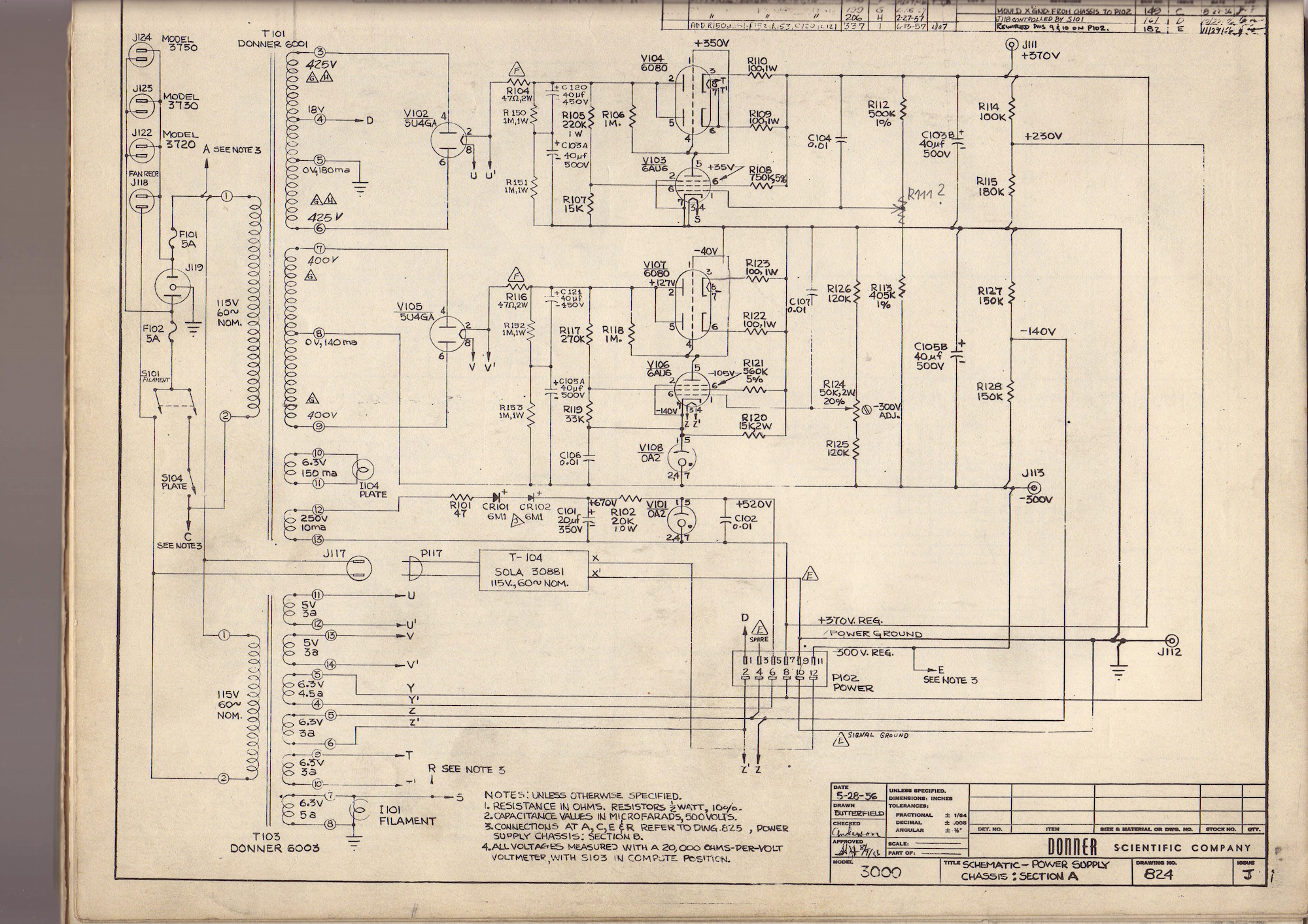
In order to switch on the computer, S101 is closed, applying power to T103 which generates most of the required filament voltages (not only for the power supply itself, but also for the amplifier chassis holding 10 individual operational amplifiers). After about a minute or two, S101 closed which powers T101. The secondary winding shown on top has two 425 V taps which are connected to a dual rectifier tube V102. The output of this rectifier is filtered and fed to a linear regulator consisting of a dual power triode V104. The grids of both triodes which are paralleled, are driven by V103 which compares the output voltage against the stabilized -300 V output (more about this in the next section). The second secondary winding has two 400 V taps feeding another dual rectifier tube and a linear regulator circuit quite similar to that described above. The main difference is the stabilizer tube V108 connected to the cathode of the pentode V106. This subcircuit generates a stabilized -300 V output which serves as a reference for the +370 V circuit above. The secondary winding at the bottom of T101 delivers 250 V and feeds a selenium rectifier CR101/102. After passing the power resistor R102, this voltage is stabilized at +150 V by V101. Since the cathode of V101 is connected to the +370 V output of the topmost linear regulator the voltage on the plate of V101 is +520 V (this was the connection that was missing).
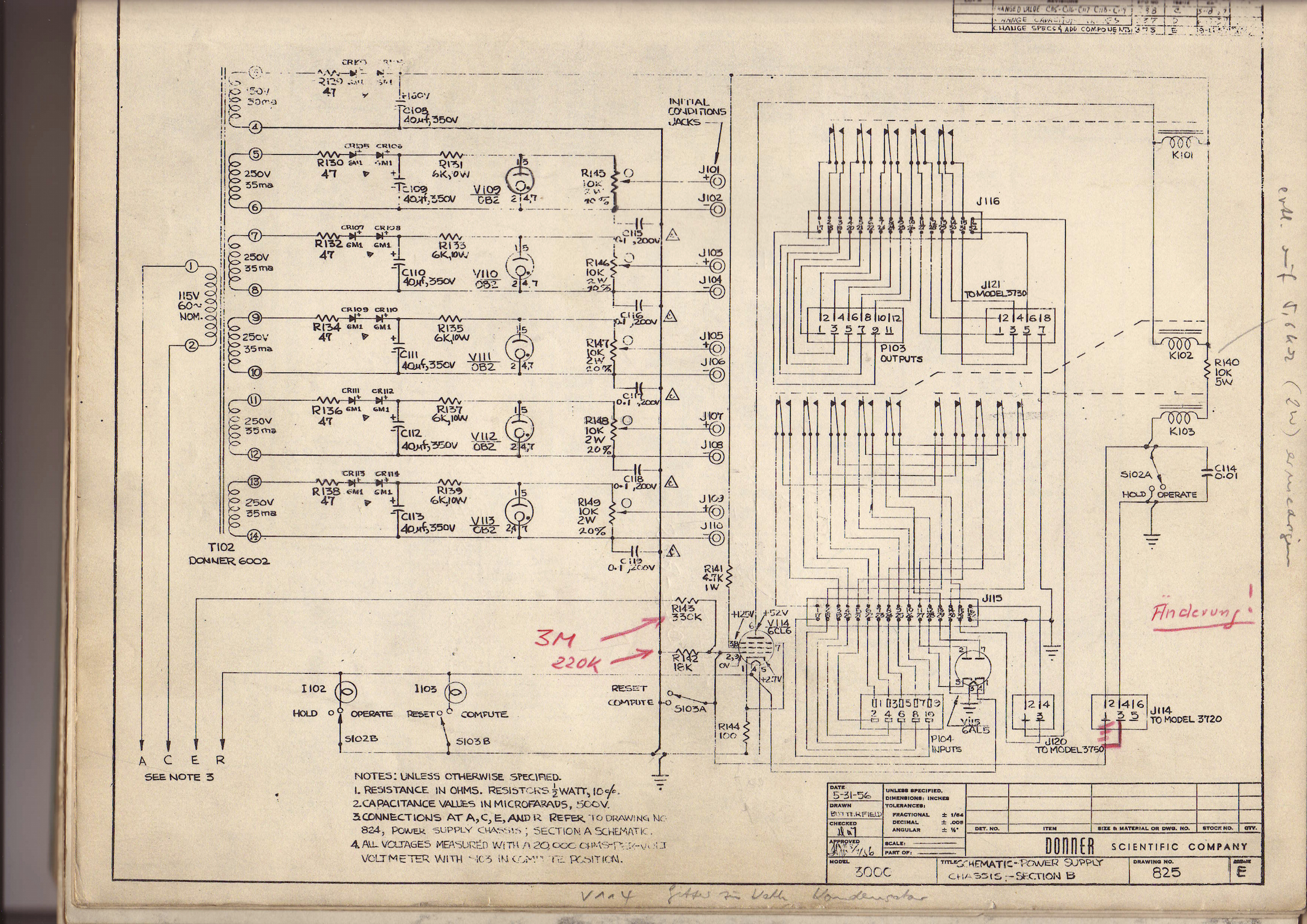
The schematic above shows the circuitry generating the five voltages for initial conditions. These are derived from the five distinct secondary windings of T102. Each of these outputs is fed to a selenium rectifier followed by a filter capacitor, a power resistor and a stabilizer tube type OB2. The actual initial condition is set by means of a 10k potentiometer connected to this stabilized voltage. The right side of the schematic shows the relays used to control the integrators. A typical integrator has three modes of operation: IC (initial condition), OP (operate), and HALT. In simple cases it is sufficient to control these modes manually, but to obtain a stable picture on an oscilloscope it is desirable to switch the integrators between IC and OP automatically. This can be done by means of an additional unit, the "Cyclic Reset Generator" which controls the control grid of V114 which in turn drives the relay controlling IC and OP mode. With the power supply fixed, it was time to turn our attention the amplifier chassis. The picture below shows the schematic of this unit:
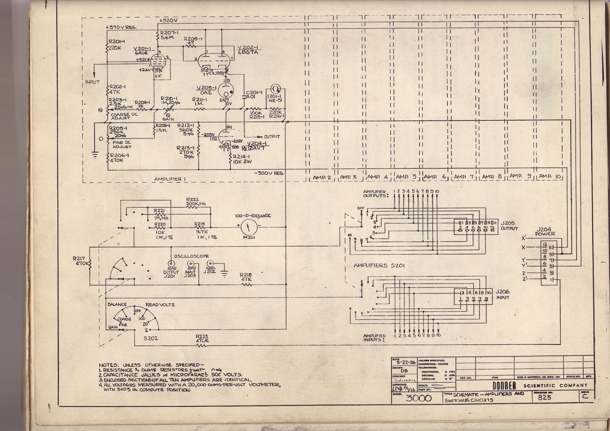
The amplifier chassis contains ten identical operational amplifiers without any kind of drift compensation. To setup the amplifiers a meter is used that can be switched to any amplifier by a set of switches. One of the ten amplifiers is shown in the upper left corner of the schematic. The design is pretty basic: The tubes V201 and V202 form a two-stage amplifier with V204 acting as a constant current source. Each amplifier has three controls, two of which are located on the inside of the chassis: Coarse DC adjust and Gain. A third potentiometer, fine DC adjust, is accessible on the front panel. Assuming that coarse DC adjust is set correctly, the fine adjustment is made before a computation when the unit has reached operating temperature. Apart from a defective tube (the getter was white, so it was clear that the tube had drawn air) and a faulty socket which prevented one of the dual-triodes from heating, this chassis held no surprises for us and worked like a charm after fixing these two minor problems. |
|
|
|
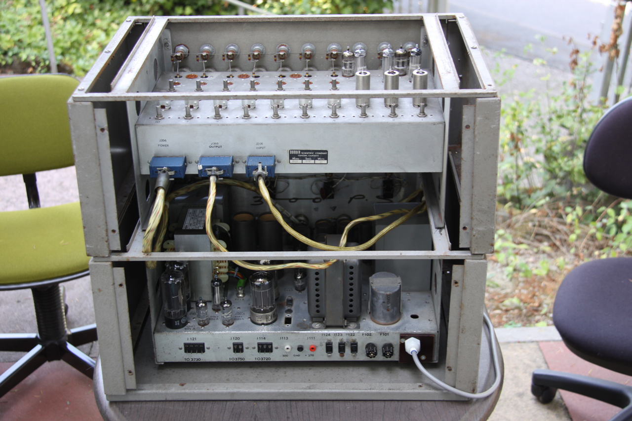
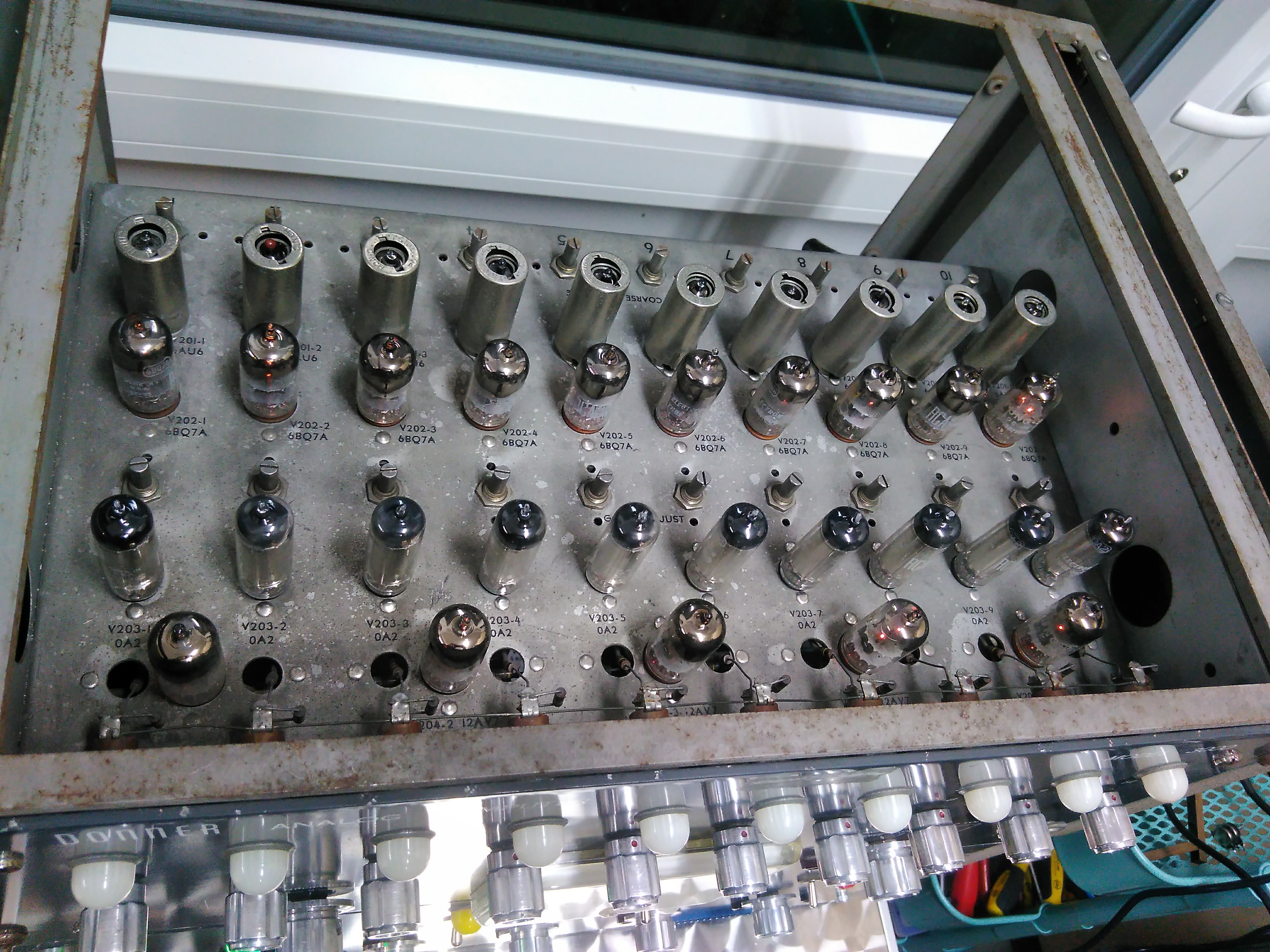
The picture on the left shows the top of the amplifier chassis. Each of the ten amplifiers consists of one 6AU6, one 6BQ7A, on OA2 and half of a 12AV7 dual triode. All in all there are 35 tubes in the amplifier chassis (and another 15 tubes in the power supply). On the top of the picture the potentiometers for coarse DC adjust are visible. The potentiometers between the 6BQ7A and the OA2 set the gain of the amplifiers. |
|
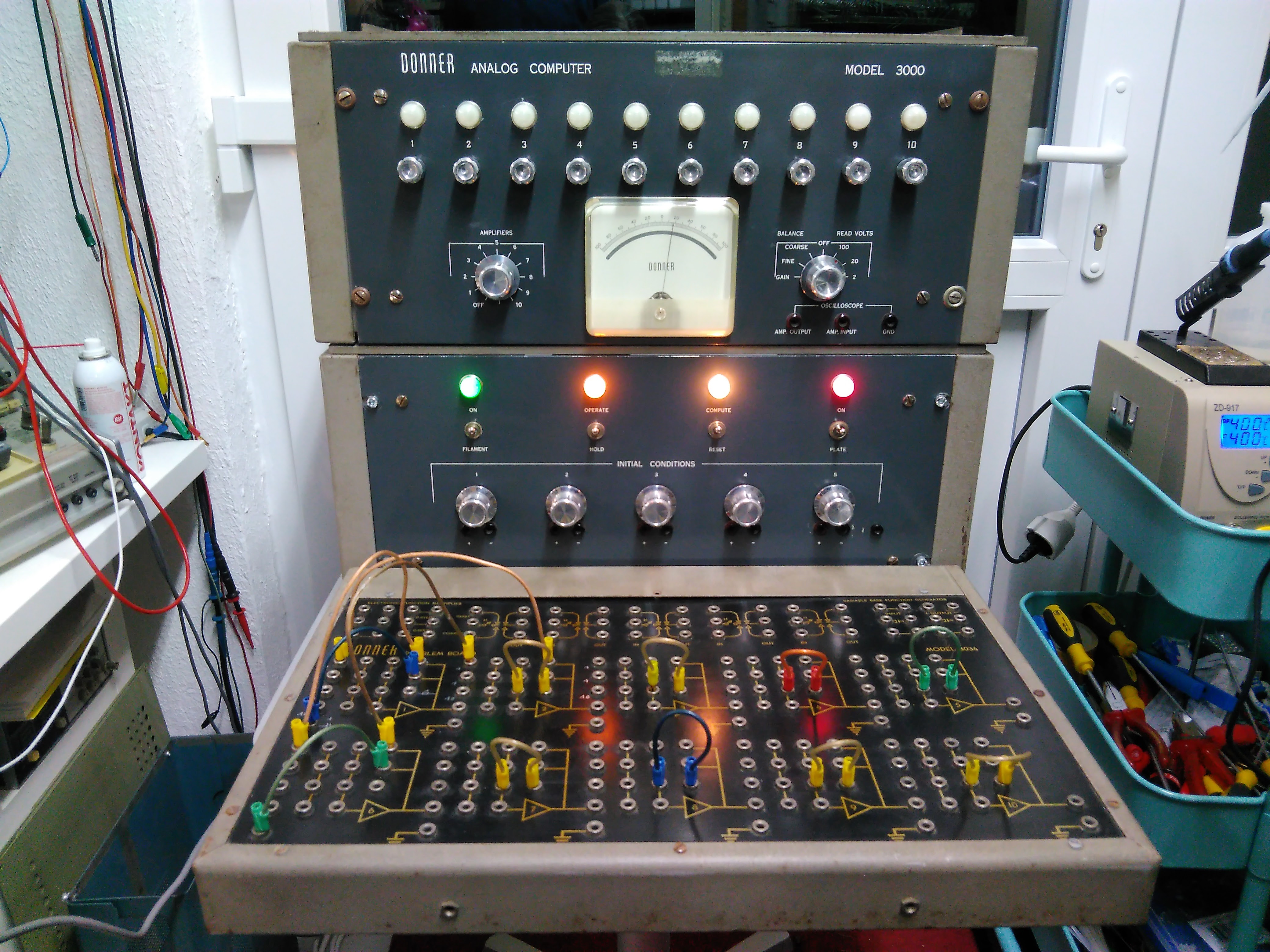
The picture on the right shows the first setup of power supply, amplifier chassis and patch panel. Originally, one had to use lots of external passive computing elements such as precision resistors and capacitors to setup summers and integrators based on the operational amplifiers. Unfortunately, I don't have any of these external components. But as I have some spare patch panels we decided to add some resistors and capacitors to unused jacks of this patch panel to simplify patching. I have to admit that this deviates substantially from the original setup but these changes can be undone easily if I ever find enough original passive elements to go with these. All amplifiers have been patched with a resistor in the feedback loop. The two leftmost amplifiers have been equipped with capacitors so that they can be setup easily as integrators as is done here. The overall circuit solves the extremely simple differential equation y = -y'' and thus generates a sine/cosine signal pair. The bright control lights on the power supply show that the filaments are turned on (leftmost, green), plate is on (rightmost, red), and the computer is currently in OP mode. |
|
|
|
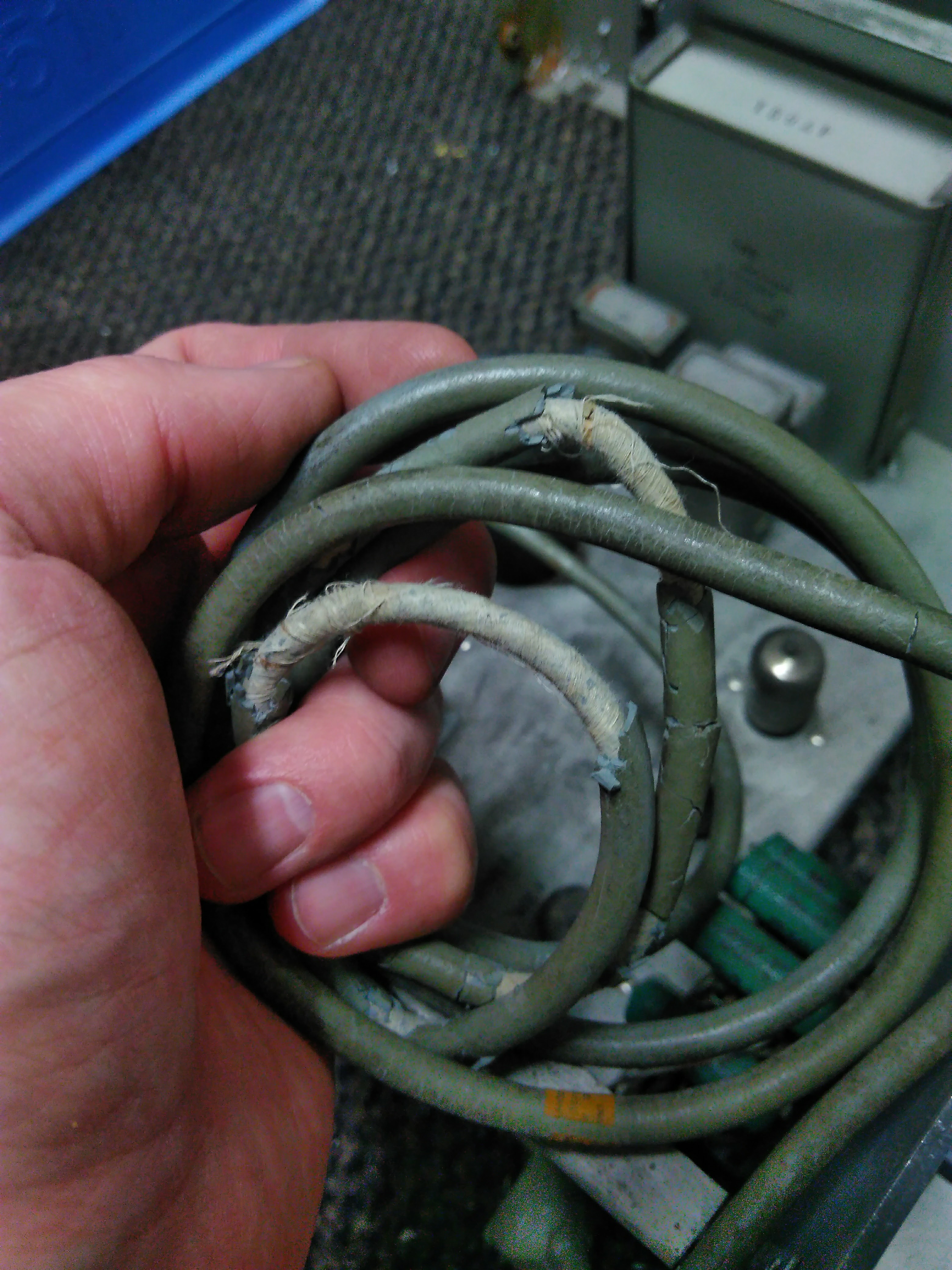
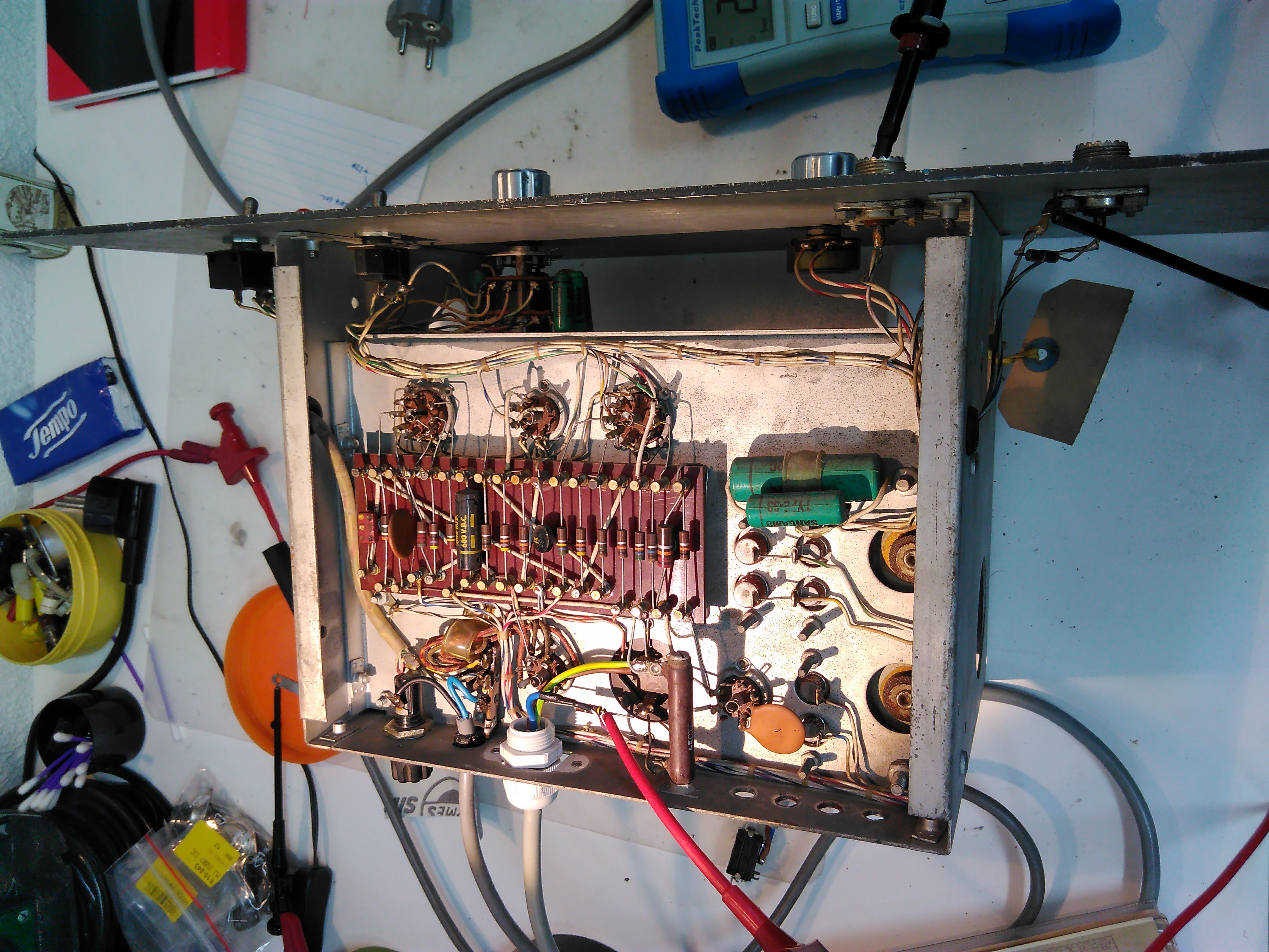
Now that the computer worked and we still had some time on our hands, we decided to have a look at the "Cyclic Reset Generator" unit which can be used to implement so-called repetitive operation. This unit is pretty simple and basically consists of a astable multivibrator, a time delay and an output driver. The multivibrator generates the clock signal which controls the IC/OP mode of the analog computer after passing through a short time delay. The non-delayed clock signal is fed to a connector on the front panel and can be used to trigger an oscilloscope or pen-plotter before switching the computer into OP-mode. A typical problem with electronics as old as these devices (built in 1958) are power cords. The picture on the left shows the power cord of the Cyclic Reset Generator. This had, of course, to be replaced first. |
|
The picture on the right shows the bottom of the Cyclic Reset Generator. The power supply is a bit strange as it is based on an off-the-shelf transformer yielding 250 V on its secondary. This is then fed to a power resistor after passing a rather big filter capacitor. Following this resistor is a stabilizer tube which finally yields +70 V plate voltage. Of course, the power resistor get really (!) hot under these circumstances. As the lower end of the power resistor, being at +250 V, was only about 1 mm from the grounded chassis away, I drilled a small piece of Expoxyd board as a spacer between the resistor and chassis. The next problem was that the cable connecting this unit with the main computer was missing. We decided to remove the connected mounted to the chassis of the Cyclic Reset Generator and use it as connector to the computer. This modification can be undone if we ever find suitable plugs and jacks for the computer. |
|
|
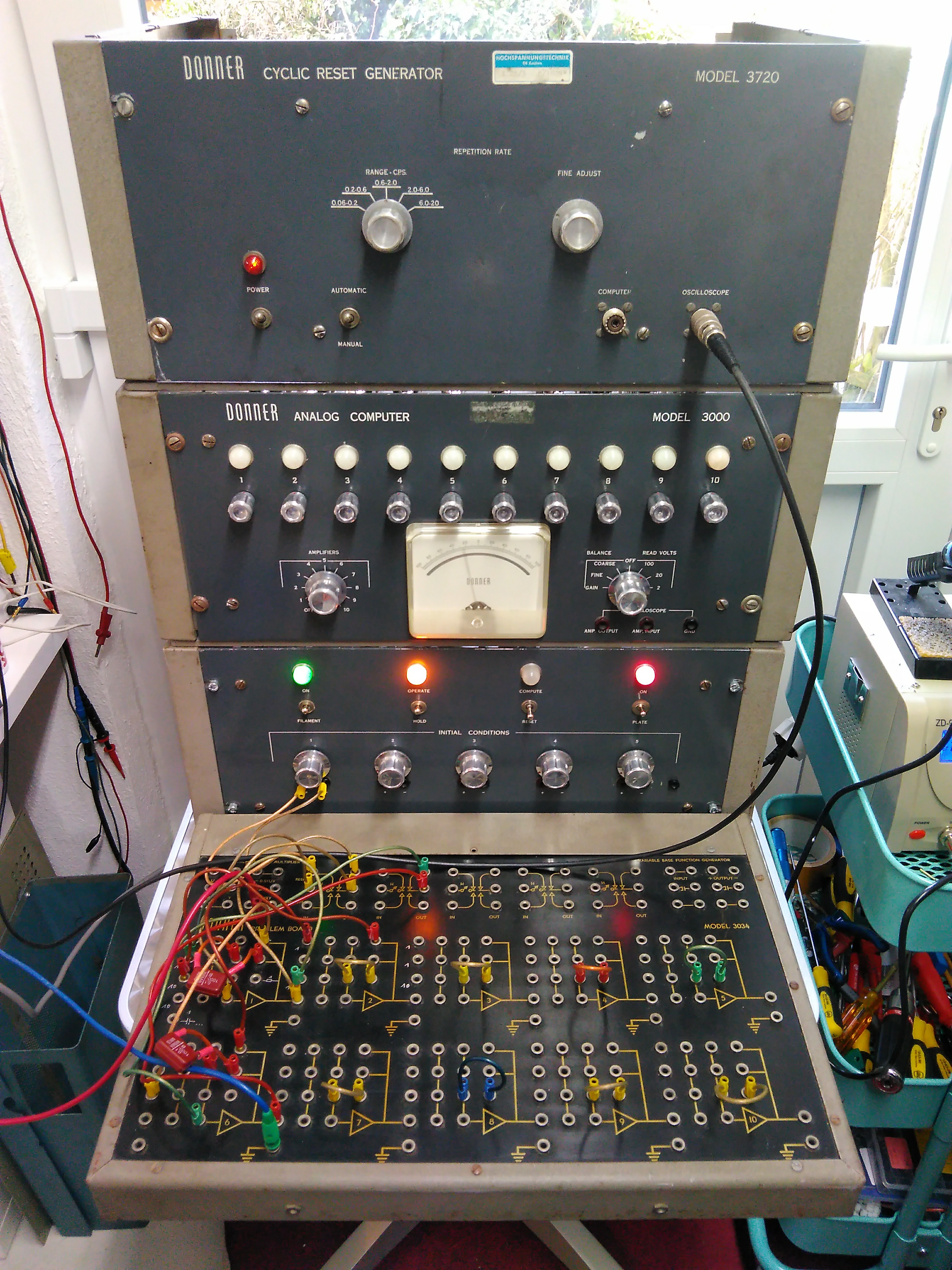
The picture below shows the result of our restoration efforts: A fully operational Donner 3000 analog computer from 1958 with Cyclic Reset Generator on top.
|
|
|
24-JAN-2016, 16-FEB-2017, ulmann@analogmuseum.org |
|