| The RA 741 |
| The RA 741 |
|
The RA741 is the direct predecessor of the TELEFUNKEN RA742 analog computer and the successor of the RAT700 analog computer. About 15 years ago my friend Christian Peters spent a whole day to help me rescue an RA741 analog computer from the university of Aachen. Since then this machine sat in my hallway and was waiting for its resurrection. Somehow I was afraid of beginning this task - do not ask me why. Last week I took one week off from work (for the first time in my life :-) ) and decided to use this spare time to try to get the system up and running again. Fortunately I had another RA741 in parts which was very useful in repairing this one. |
|
|
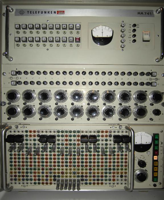
Whenever I attempt to restore an old computer I will never just switch it on - it is way too dangerous since failures and errors might destroy other circuits leading to sheer never ending trouble. So the first thing I always have a look on is the power supply which is located in the right half of the upper drawer shown in the picture on the left. The left half of this drawer contains fifteen of the operational amplifiers of this computer. |
|
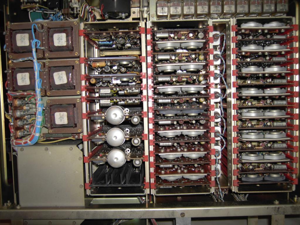
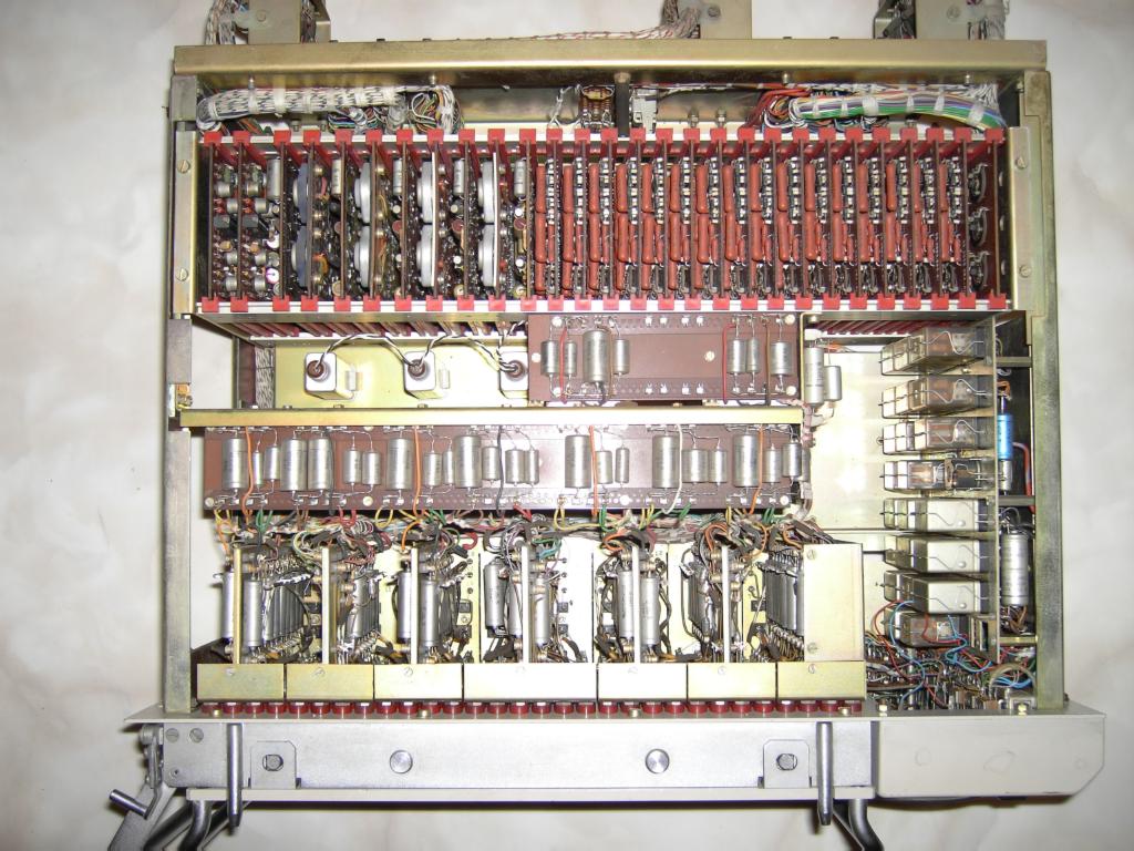
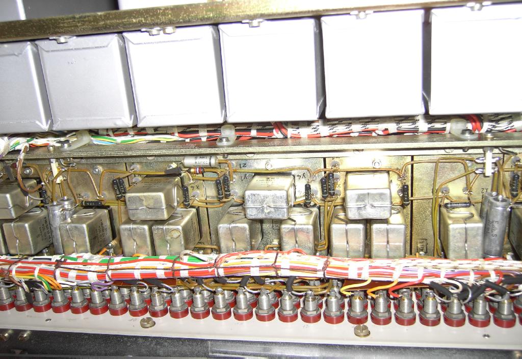
The picture on the right shows the innards of the upper drawer (the front panel is on top of the picture). On the left hand side are the large filter inductors and the silicon rectifier diodes. Next to this is a card cage holding the regulator cards and some additional circuitry for the power supply. The two card cages on the right hand side of the picture hold the 30 cards representing the 15 operational amplifiers. Each amplifier consists of a main amplifier and an auto-zero (support) amplifier as well as one half of a chopper relais (these special purpose relais can be seen between the two operational amplifier card cages). |
|
|
To understand the following odyssey a tiny bit of theory concerning the implementation of low drift (auto zero) amplifiers is required. |
|
|
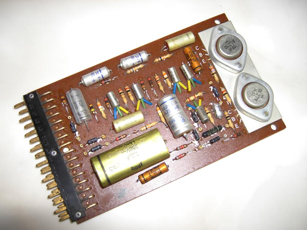
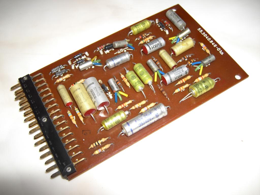
The picture below left shows the main amplifier part of an operational amplifier of the TELEFUNKEN RA741. On top of the card are two high power Germanium transistors which form the output stage of the amplifier. This card alone could act as an operational amplifier (with quite impressive technical data even for for today's standards). But this amplifier would suffer from drift as every simple operational amplifier does. Drift is a real problem in analog computation since errors caused by (temperature) drift effects will accumulate in the integrators and render calculations useless. In normal consumer applications this drift poses no problems since all amplifiers in these application areas are capacitively coupled to their surrounding circuitry so DC drift is no problem at all. |
|
An electronic analog computer like the RA741 requires DC coupled operational amplifiers for solving equations, so every tiny drift voltage will have an influence on the calculation and must be taken care of. This led to the development of (nearly) drift free amplifiers which are called auto-zero amplifiers sometimes. The idea behind this is as follows:
|
|
|
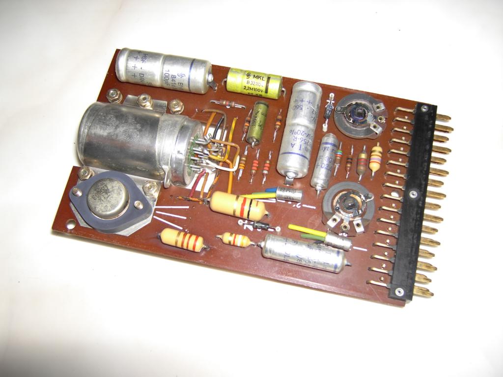
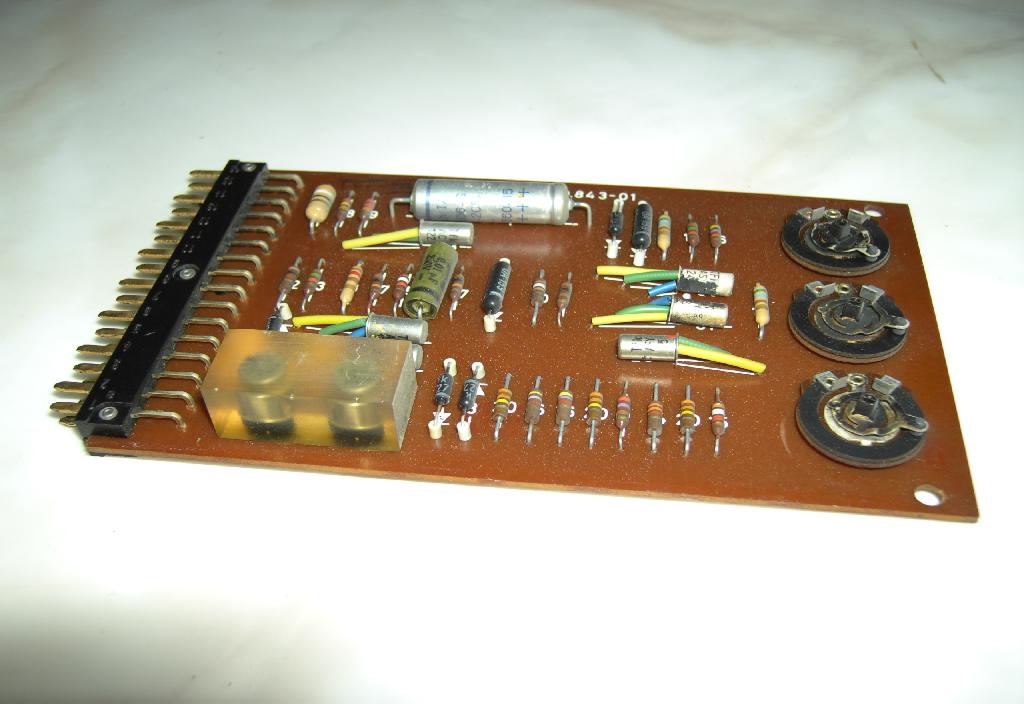
The picture on the right shows the support amplifier which is used to amplify the drift signal present on the summing junction of the main amplifier shown above. The input signal to this support amplifier has already been chopped by the electromechanical chopper relais so this amplifier can be connected as an AC coupled (and thus drift free) amplifier. The output signal is then rectified (note the two black Germanium diodes on the left hand side of the printed circuit board) and fed back to the main amplifier. |
|
|
And now to the power supply: It generates three types of voltages:
|
|
Having set the stage the drama can begin. :-) When I first switched on the upper drawer (removed from the rack), all voltages very erroneous (prior to this I removed all 15 operational amplifiers to make sure those would not be damaged should something really go wrong in the following).
Fortunately the first thing I did was to have a look at the two 400 Hz voltages for the choppers and the synchronous rectifiers. The chopper voltage was there and looked quite good. The rectifier control voltage looked horrible and was only 200 Hz which was interesting since both voltages are derived from a single signal source. :-) It took me about two hours to understand the 400 Hz generator circuit - just to realize that it should work but it did not work. Half an hour later I found out - by mere accident - that one of four potentiometers needed to set frequency and phasing had deteriorated during the last 40 years (that is not what I would call quality :-) ). Cleaning the slider and the sliding surface cured that and both voltages had the correct waveform at the outputs of the 400 Hz generator card. |
|
|
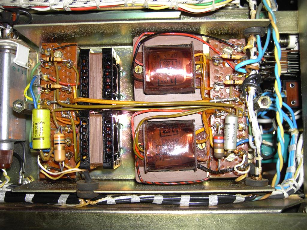
But nevertheless, the problem remained - the rectifier control voltage looked awful and not a bit like a square wave as it should. It turned out that the 400 Hz voltage amplifier shown in the picture on the right was defective, too. This amplifier is an interesting device (apart from the fact that it is shown only as a white rectangle on the drawings). It is a push pull amplifier with transformers for decoupling and it quite closely resembles an audio amplifier of the 1960ies. It turned out that one of the power transistors driving the pull side of the circuit was defective. (In the picture four transformers can be seen - the two small transformers on the left side are part of the rectifier control voltage amplifier while the two transformer on the right hand side are part of the higher power chopper voltage amplifier.) |
|
|
Alas - the +/- 10 V power supplies still did not deliver +/- 10 V. So I turned my attention to the two operational amplifiers (again) - this attempt can be seen in the picture on the left (please note the yellow cable leading to the upper plug on the back of the drawer - whenever you want to run the upper drawer removed from its rack, be sure to ground pin A4 of this jack to energize relais 2 which will cause the internal voltage reference to be used - otherwise the +/- 10 V levels will be undefined - this feature is used to connect several RA741 in parallel with one computer being master and defining the signal levels). After some experimentation it turned out that both operational amplifiers were defective (by the way - here only the support amplifier part of a complete operational amplifier is being used - the voltage regulator acts as the main amplifier). |
|
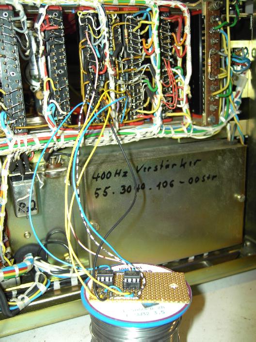
After looking at the two circuit boards and realizing that I am really short of proper Germanium replacement transistors I decided to make an accomodation - I would try to use two modern, of the shelf operational amplifiers instead of the two printed circuit boards full of Germanium transistors and diodes (it was about 2 AM when I decided to do this :-) ). By thew way - should you happen to have some spare Germanium transistors left (AC12x, AC17x, etc.), please do not throw them away - I would be glad to give them a new home if you want to get rid of them. :-) The two pictures below show my solution. In the picture on the left two OPA27 integrated circuits mounted on a small piece of pertinax board can be seen. It turned out that these two amplifiers worked perfectly in this ciruit so I decided to quit thinking about debugging the two original operational amplifiers and use this solution instead. The picture on the right shows the final solution - the two OPA27 have been mounted on the frame of the 400 Hz amplifier (the writing on the case is not from me). Please note the empty tube-like relais socket on top of this contraption. This is where the now useless chopper relais was mounted which supported both of the regulator amplifiers. |
|
|
|
|
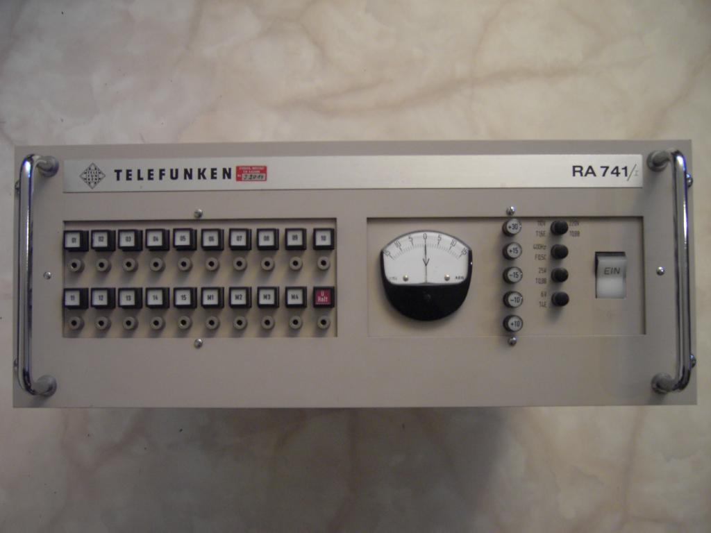
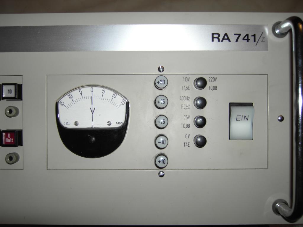
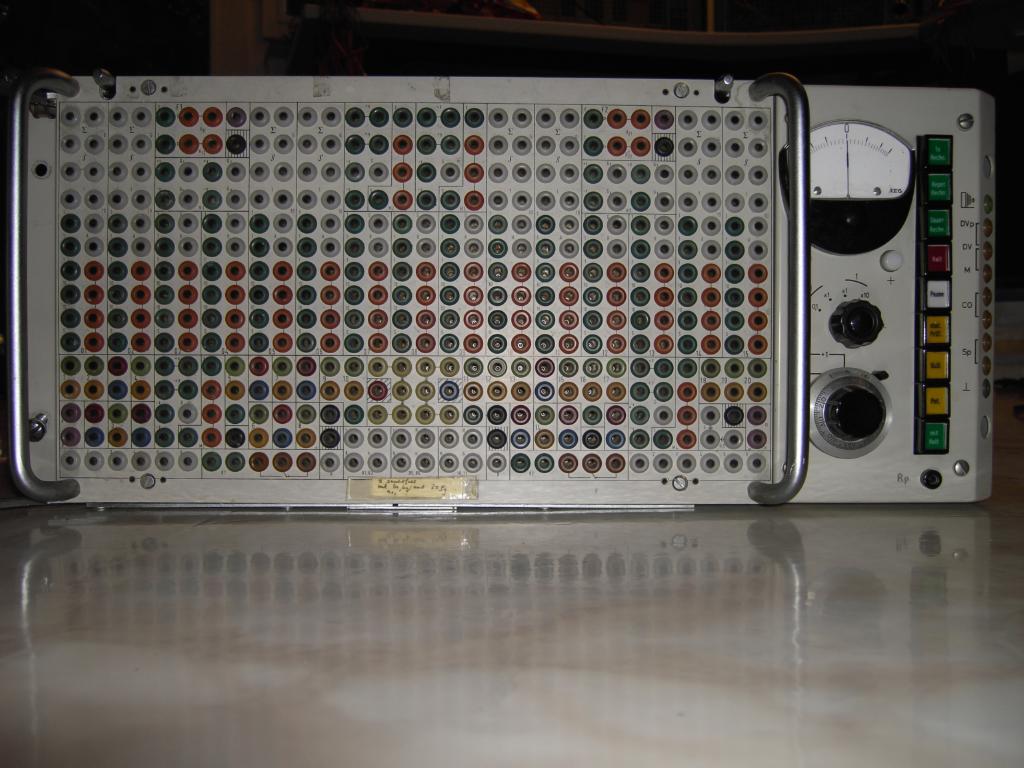
The picture on the right shows the front plate of the power supply part of the upper drawer. When powering it on all voltages are present after a couple of seconds (when you do this and hear a relais clicking for some seconds, this is perfectly normal - TELEFUNKEN used a relais to artificially unbalance the +/- 10 V regulators to force the circuit into regulation - so these two voltages will come last and only after the clicking stops). |
|
|
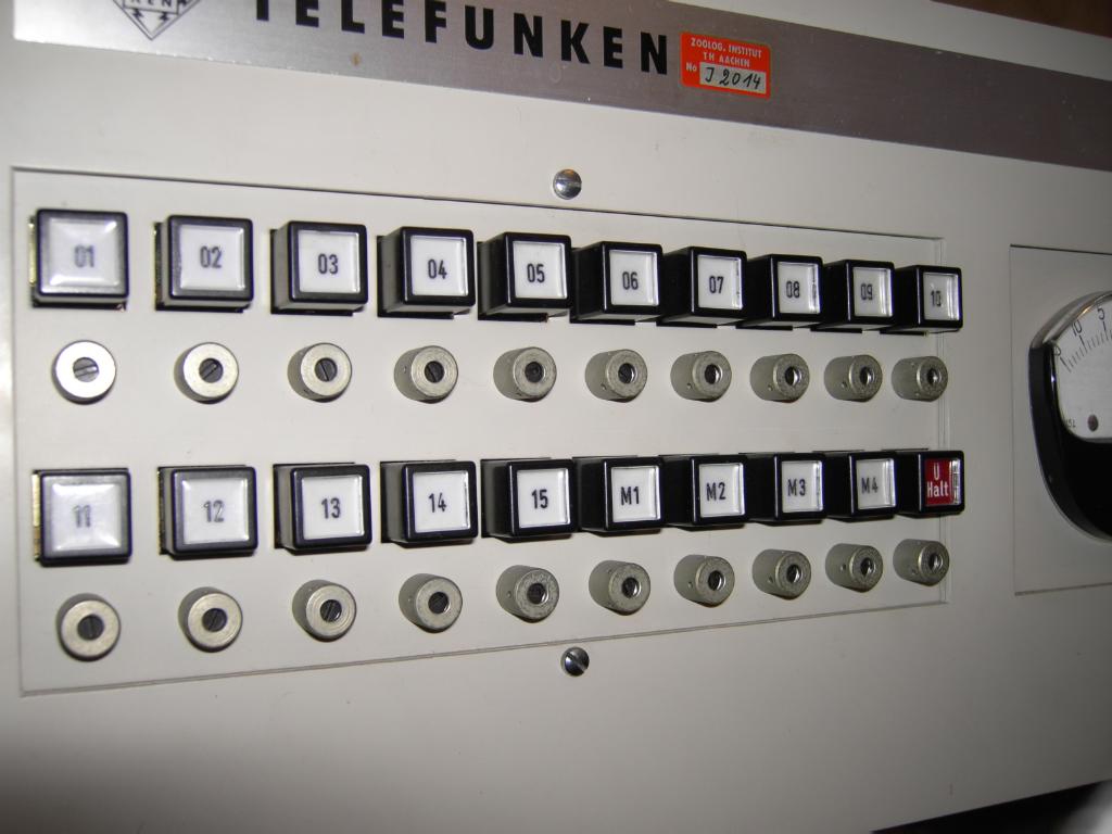
After fixing the power supply I inserted the 30 cards of the 15 operational amplifiers. The picture on the left shows the front panel of the amplifier half of the upper drawer. Each amplifier has one overload indicator (a push button which will cause the output of the amplifier to be connected to the readout bus when depressed) and one balance potentiometer (below the push buttons). When switching this drawer on, all overload indicators should light for a moment and then extinguish. Some of mine did not but fortunately I had three spare amplifiers which I used as replacement parts. After swapping these boards in, the upper drawer was operational again which I checked by testing each amplifier with a 1 kHz sinusoidal input signal of 100 mV amplitude as input. Each amplifier got its own feedback network to ensure an amplification of ten as a test bed. |
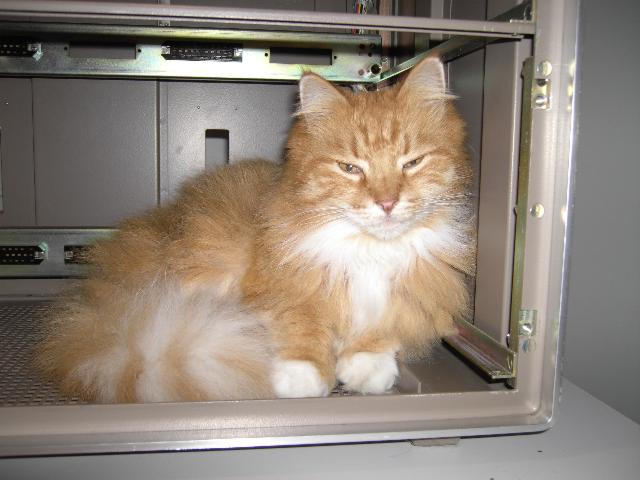
| Now, time has come to put the upper drawer into the empty rack which can be seen in the picture below left. The only problem which I had to face now was that the rack was not really empty when I came with the upper drawer from my working room - obviously I am not the only one with a weakness for (old) analog computers - my cat Johnessey was not amused to find out that he had to leave his new home. :-) | |
|
|
|
|
The next drawer I started working on was the lower drawer shown on the right. This drawer contains the removable patch panel (quite a tricky construction which will be shown soon) as well as the central control elements to select the compute modes and times (on the right hand side of the picture). Note that this drawer contains all of the control logic in form of dozens of relais which makes debugging quite complicated since relais allow many trick circuits which are unusual for people who have grown up with TTL logic devices. :-) |
|
|
The picture on the left shows the top view of the lower drawer (the patch panel is at the bottom of the picture). On top of the picture the card cage holding two relais comparators, four operational amplifiers (for the parabola multipliers), the sixteen parabola function cards comprising four multipliers and the special comparator for the timing generator can be seen. Below left of this card cage three chopper relais can be seen. Below this the precision resistors and capacitors of the summers and integrators are located. |
|
The main timing control of this analog computer is based on its integrator number 15 which is placed into a special timing mode according to the settings on the control panel. This integrator will generate a ramp from -10 V to +10 V. When it reaches +10 V, the compute cycle will be stopped and the computer will either halt or start the next compute cycle. At the heart of this circuit is a precision comparator which can be seen in the picture on the right. Please note the epoxy block containing two transistors - this was not done to couple them thermally together, it was rather done to prevent changing only one transistor of this matched pair. Should one transistor fail, always both transistors had to be changed. |
|
|
When I started to check out this lower drawer new problems appeared. Two integrators, 10 and 11, were inoperational. These amplifiers worked fine when set to summing mode but their output just remained at zero when set to integrator mode regardless of their initial condition and input values. My focus turned to the control relais section which is shown in the picture on the left. If turned out that everything just worked fine as long as the drawer was not mounted in the rack and all connections were made on the test bench... |
|
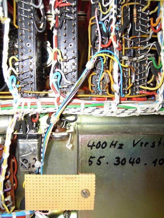
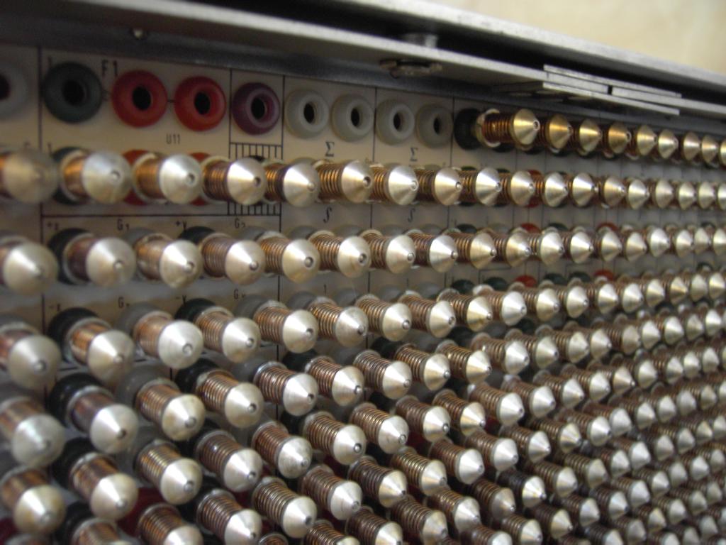
The problem turned out to have its cause behind the removable patch panel! TELEFUNKEN used a rather complicated method to implement removable patch panels on their table top analog computers. The picture on the right shows a view behind the panel - I removed some of the plugs. As can be seen there is a non-removable patch panel behind the removable patch panel. Every plug has a jack with a spring which makes contact to the plugs of the removable patch panel... At least it should make contact. After cleaning hundreds of those fragile spring constructions suddenly the control circuit was working again - the problem was just caused by corrosion... |
|
|
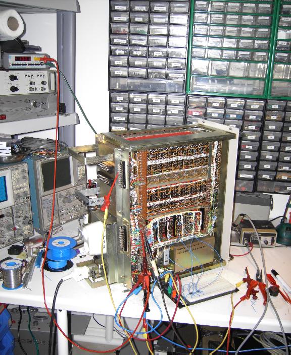
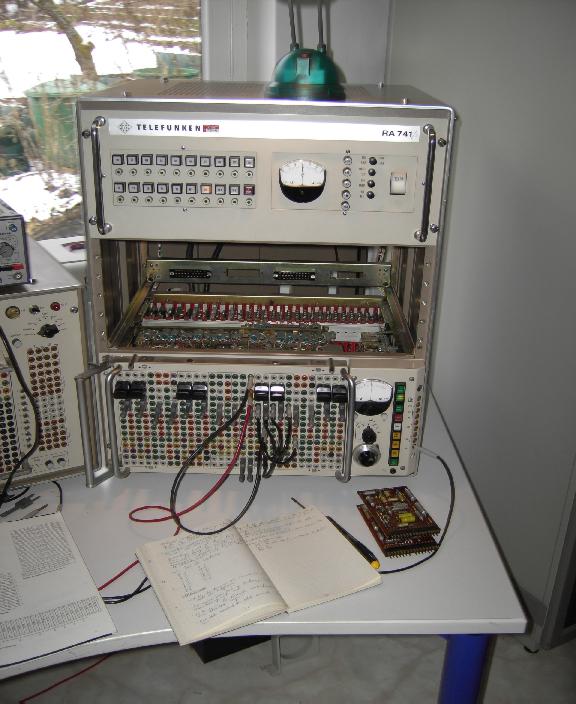
After both the upper and lower drawer were operational again I mounted them in the rack and the resulting system looked like shown in the picture on the left. As you can see I made a simple test circuit to test all of the computational amplifiers one after the other. |
|
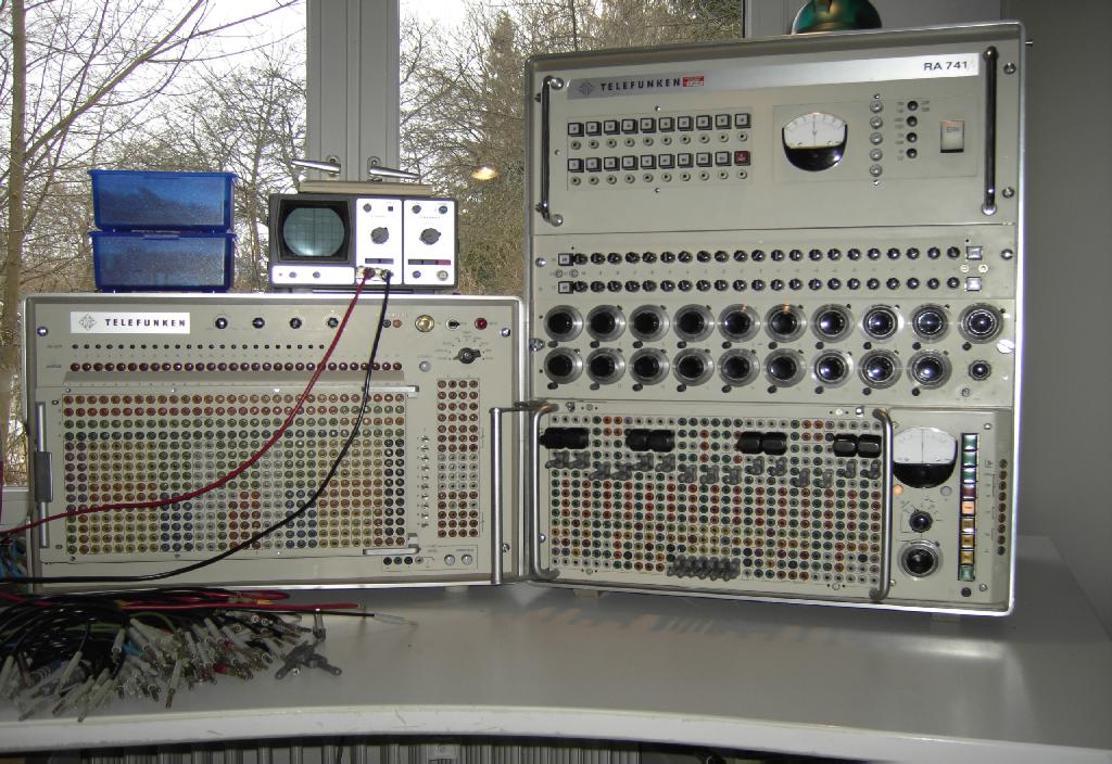
After these tests were successfully completed, I reinserted the middle drawer containing the two variable function generators and the 20 coefficient potentiometers (which are very deteriorated - if you ever have some spare 10 turn potentiometers, please let me know :-) ). The resulting system can be seen in the picture on the right - on the right hand side is the RA741 in all of its glory. Left to it is a DEX100 which has not yet been connected to the analog computer. On top of this sits a small oscilloscope. |
|
|
All in all this restauration effort took me three whole days (and most of the nights, too :-) ), it made me a bit wiser concerning some TELEFUNKEN circuits and it caused me some additional grey hair. :-) All in all it was a wonderful project and I am incredibly happy to see this wonderful machine being operational again after tens of years sitting in various storage locations and I am really looking forward to solve some differential equations on this wonderful system. Please, when you hear or know about an analog computer looking for a good new home, send me an email. I do my very best to save these wonderful machines from scrap and I will always try to get them up and running again. |
|
| 27-FEB-2006, 26-JAN-2008 |