|
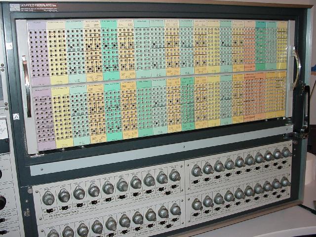
The following pages are devoted to the Hitachi 240 analog computer - a really wonderful machine which invites to play with it and solve differential equations. I would like to thank Rene' Uylenhout who donated this machine and Hans Kulk who not only collects analog computers as I do but made the initial contact between Rene' and myself to save the machine. The picture on the left shows the main part of the machine - the analog patch panel where most of the programming takes places and the coefficient potentiometer panels below which are used to set up the variables used during computations. The Hitachi 240 supports 40 chopper stabilized amplifiers (in contrast to the Hitachi 220 which has only 20 amplifiers), 40 potentiometers, variable diode function generators, multipliers, logic building blocks, etc. More about the modules will be found at the end of this page. |
|
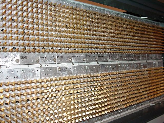
The pictures to the right shows all of the modules mounted behind the removable analog patch panel. The contacts between the modules and the patch cables are made by plated metal contact fingers against which the cables are pressed when the panel is inserted. Each module has its corresponding front template on the patch panel which is color coded to simplify programming. An integrator, for example, has a green template, an operational amplifier a yellow one, etc. The modules are layed out in a manner that allows the extensive usage of bottle plugs for programming since all patch holes are equidistant and about sixty percent (according to Hitachi documentation) of all necessary interconnections to solve a given problem can be setup using bottle plugs instead of lengthy (and thus quite sensitive) patch cables. |
|
|
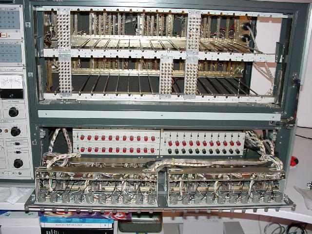
The picture on the left shows the right part of the machine with all of the modules removed (the few missing modules are interconnection modules which provide access to the potentiometer bays, the function generators, etc.). Further more the potentiometer panels have been lowered to show the setup potentiometers with red knobs of the variable diode function generators located behind the potentiometer panels (accessing the function generators is a bit tedious). Behind these function generators are the main power supplies of the machine (not visible without disassembling nearly the whole machine). |
|
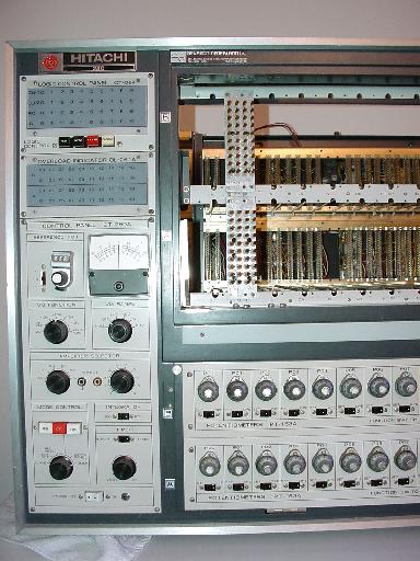
The picture on the right shows the left part of the Hitachi 240 computer. This part contains the control elements for readout selection, integrator control, overload display for the operational amplifiers, etc. From top to bottom the following units are visible:
|
|
|
On the left the coefficient potentiometer bays are shown - there are four bay of ten potentiometers each. By the way: The analog patch panel is divided into fours sectors, too, with a one to one correspondence to the potentiometer bays. Below each potentiometer is a small switch which is used to facilitate setup of the potentiometer in a computing circuit. In the setup position the input of the potentiometer is hard wired to +10V, while the output is connected to a reference circuit consisting of the precision potentiometer located on the control panel and the zero meter. To set a potentiometer to the precalculated value necessary for some given computation, the desired value is first set on the reference potentiometer. In the next step the potentiometer to be set up is selected by pushing its associated setup switch. Then this potentiometer is turned until the zero meter shows no difference between these two potentiometers. |
|
When I got the machine from Rene' it was sitting in his garage for quite a long time and collected dust (and fortunately dead spiders). After moving it to the first floor of my home (which was really hard due to the high weight of the machine which weighs in eccess of 100kg and is quite bulky) I started to test all of its modules and units to bring it to a fully functional state again. To learn about the machine I decided to start with the potentiometer bays which are the simplest parts of the machine. As it turned out this was indeed the simplest but the most troublesome part as well. The picture on the right shows one of the setup switches mentioned above. As can be seen, the orange-white wire in the middle of the switch is not even soldered to its contact - this has to be an error of production - the machine was quite obviously delivered like this in 1970. And I am sure it worked flawlessly for many, many years. But the long storage in the garage made the contact and wire corrode a little bit thus giving no reliable contact any longer which was the reason for a long debugging session. |
|
|
The picture on the left shows the machine one day after arriving at its new home. It is partly dismantled to allow access to all modules and most of the cabling. It turned out that there is a lot to do to bring the machine back to a working condition. Apart from the never soldered wire shown above, most of the switches were quite corroded, thus I cleaned all of the internal contacts of the switches with a piece of lint and alcohol and applied some special oil for electric contacts afterwards. The next problem was a erratic acting neon bulb in the overload indicator panel. Sometimes indicator 1 would light way too bright, sometimes it worked as expected. After some time it did not light any longer at all. Careful investigation showed that one of the leads of the indicator bulb was too long and barely touched the enclosing of the display unit thus shorting the control circuit. As a result the bulb was applied to 90V without the necessary series resistor and burned out. Replacing this bulb was horrible since this part of the machine was not designed with maintainance in mind. |
|
The list on the right shows all of the major modules of the Hitachi 240 analog computer. All of these modules mount directly behind the patch panel and have been removed for taking pictures of the modules. |