|
During the last couple of days I had the real pleasure of building the small analog computer developed by Dr. Vogel (a detailed description may be found in the library section of this web site). I would like to thank Dr. Vogel for donating a set of printed circuit boards which were the basis for the following. The following pictures show how this truly wonderful small computer was built: |
|
|
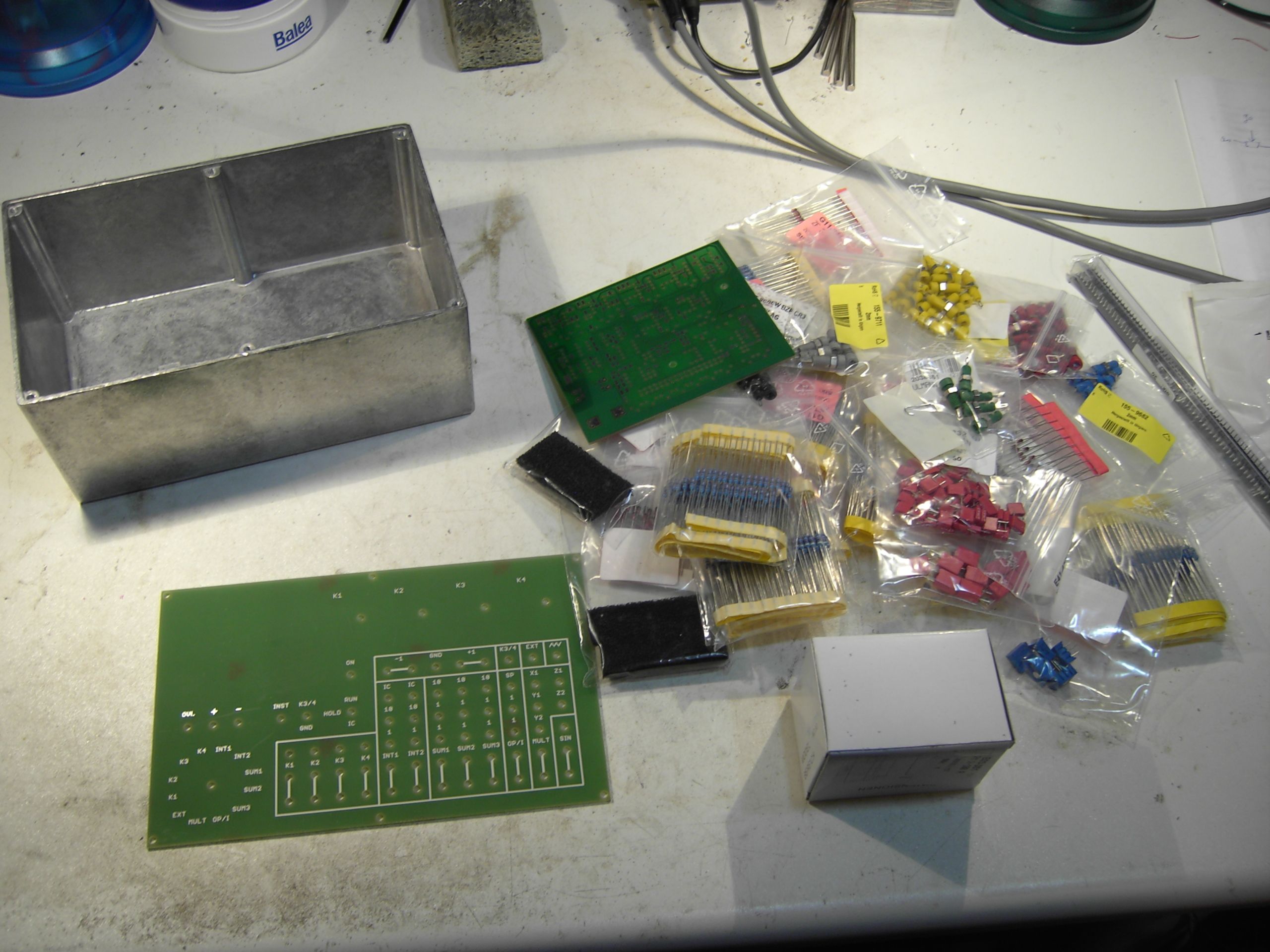
The picture on the left shows the parts (at least most of them) - some parts were found in my stash but others like the aluminum enclosure, the 2mm jacks, some resistors etc. had to be bought. |
|
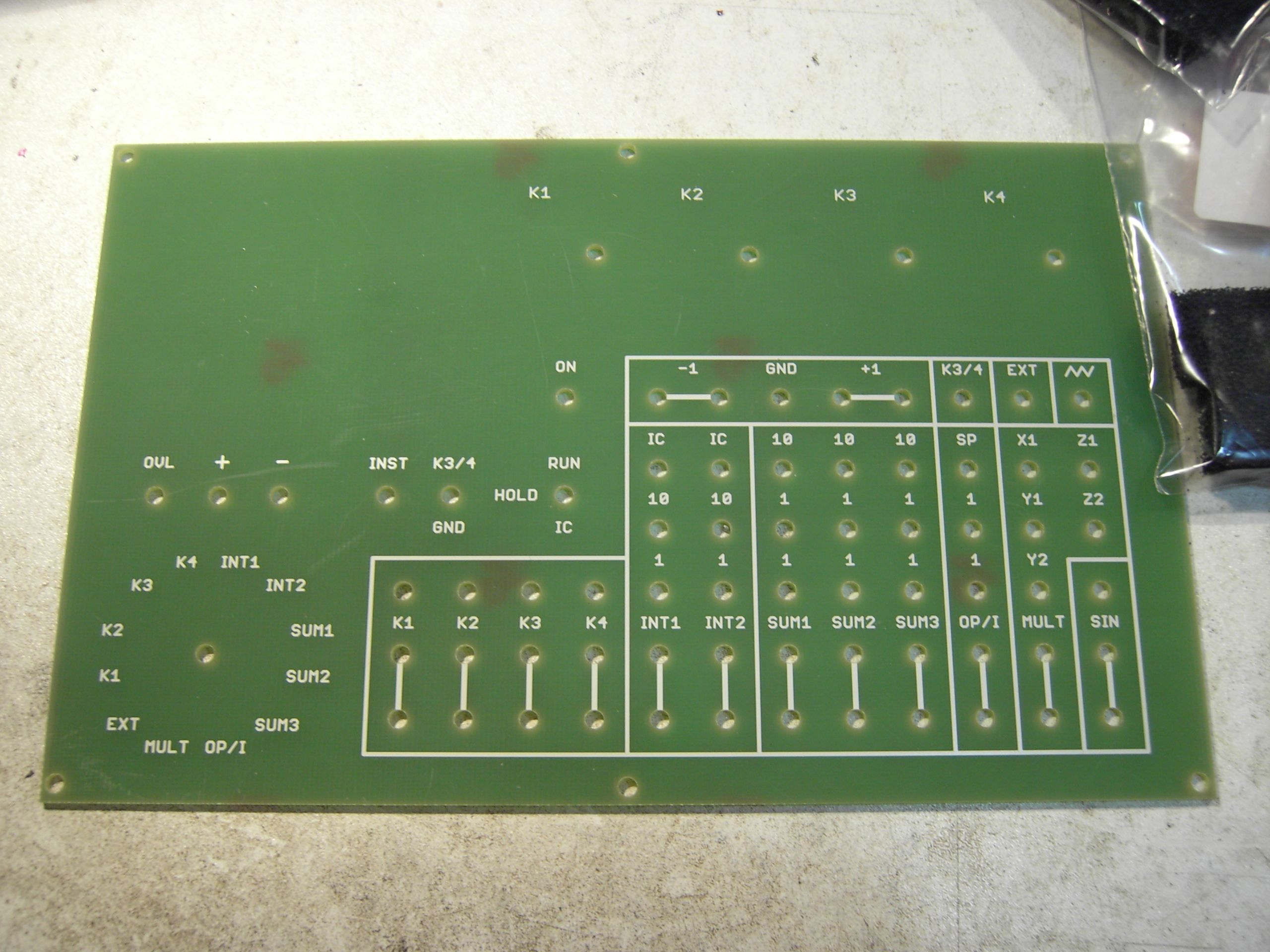
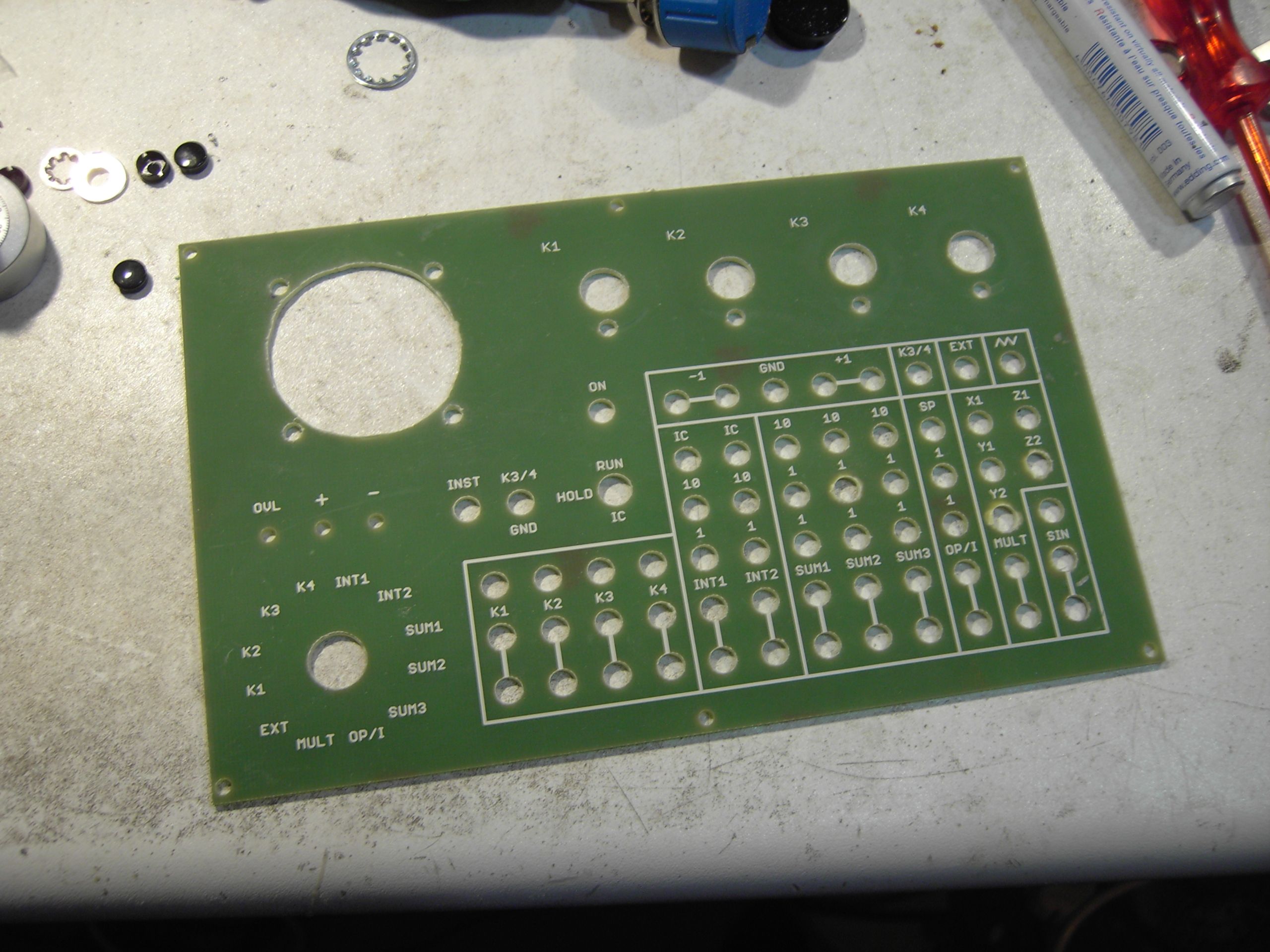
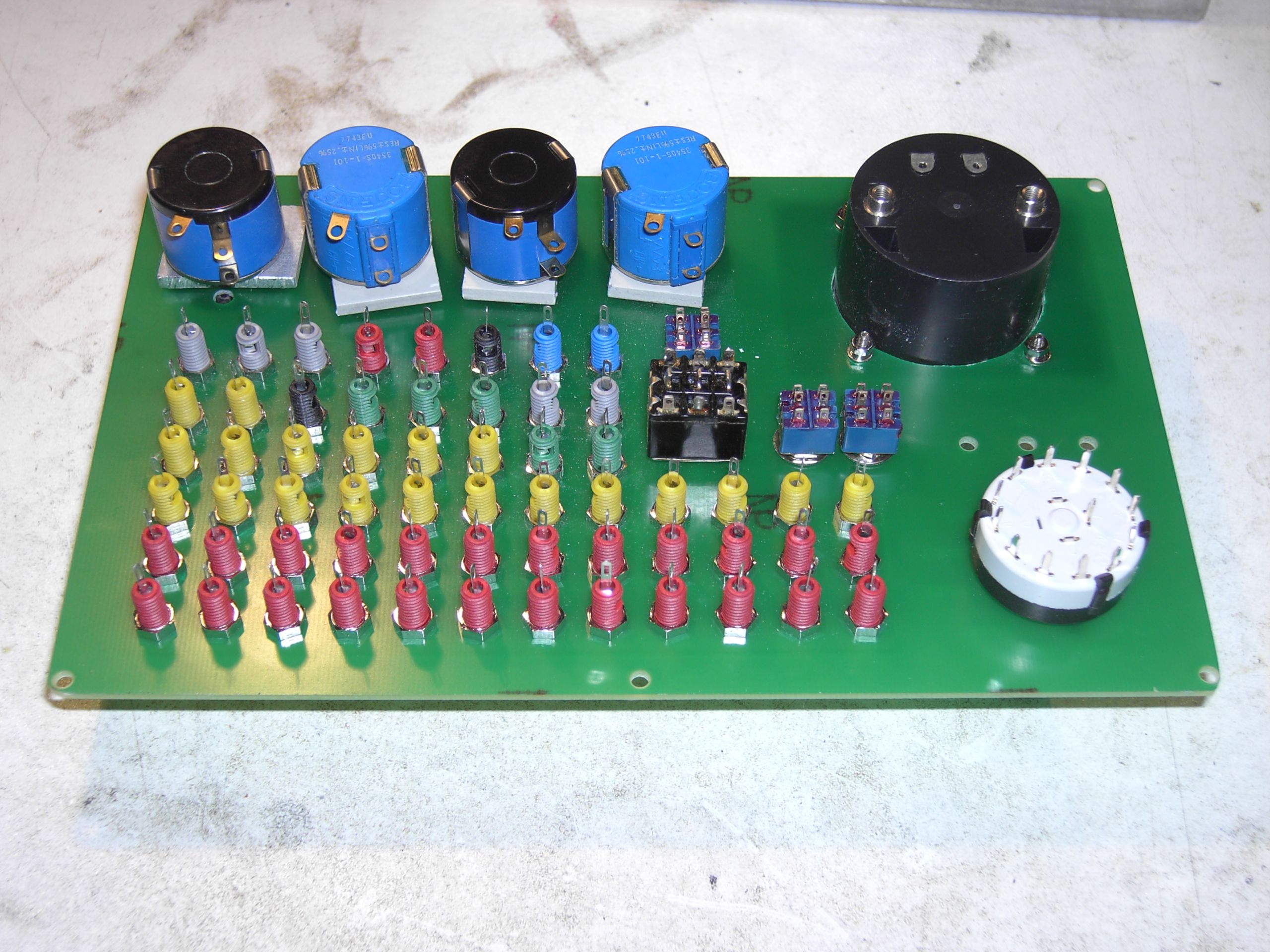
The following pictures show the frontplate with its original holes and the enlarged holes as well as the completed patch panel from front and back perspective. As it turned out the printed circuit board material was too thin to hold the 10-turn precision potentiometers, so I had to make four spacers from an old front plate which can be clearly seen. |
|
|
|

|
|
|
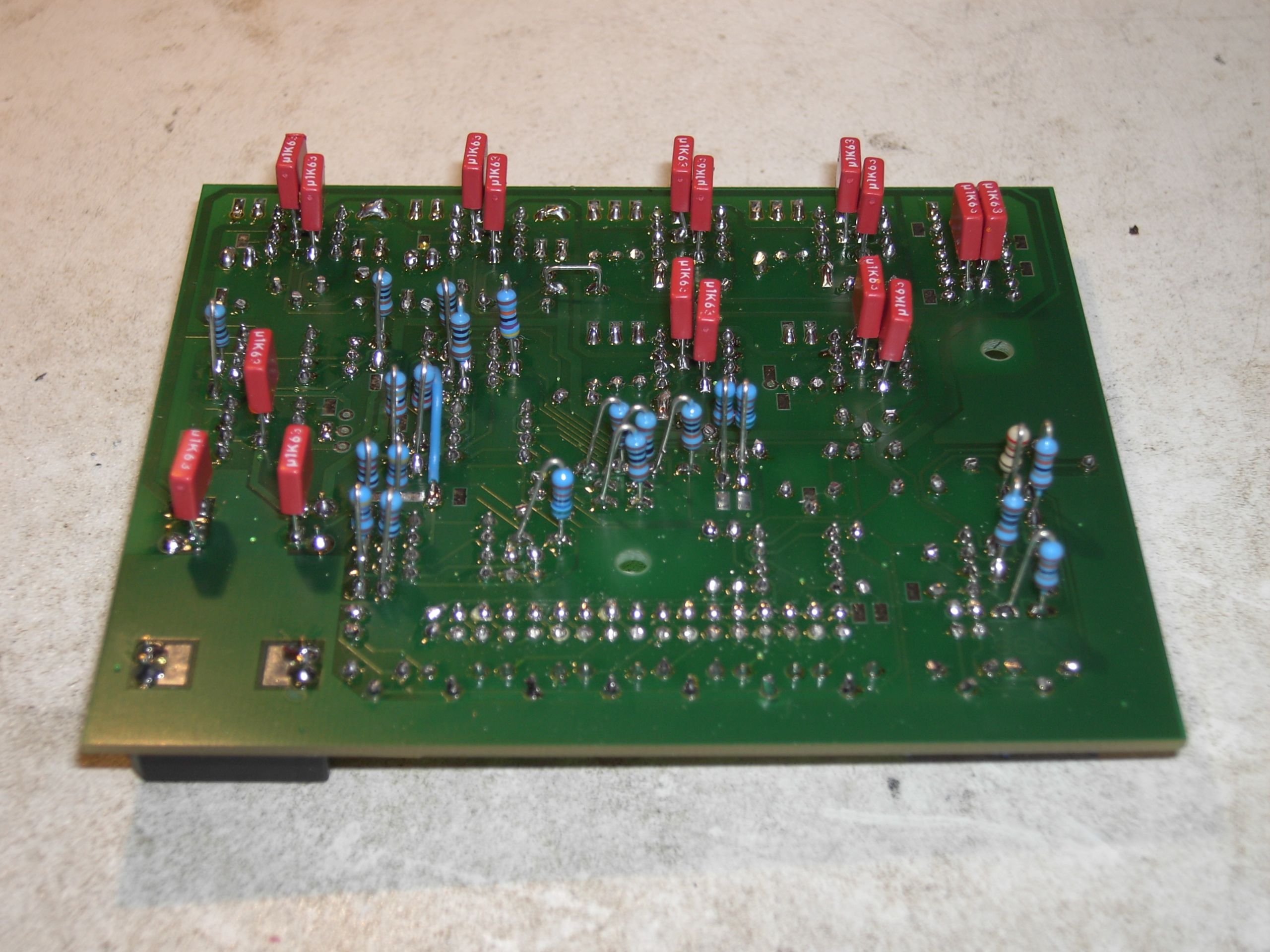
The following pictures show the completed main board from both sides. Since I had no SMD resistors at hand (and, by the way, my hands are trembling too much to work with SMD parts :-) ), I used normal axial resistors which worked out quite well. |
|

|
|
|
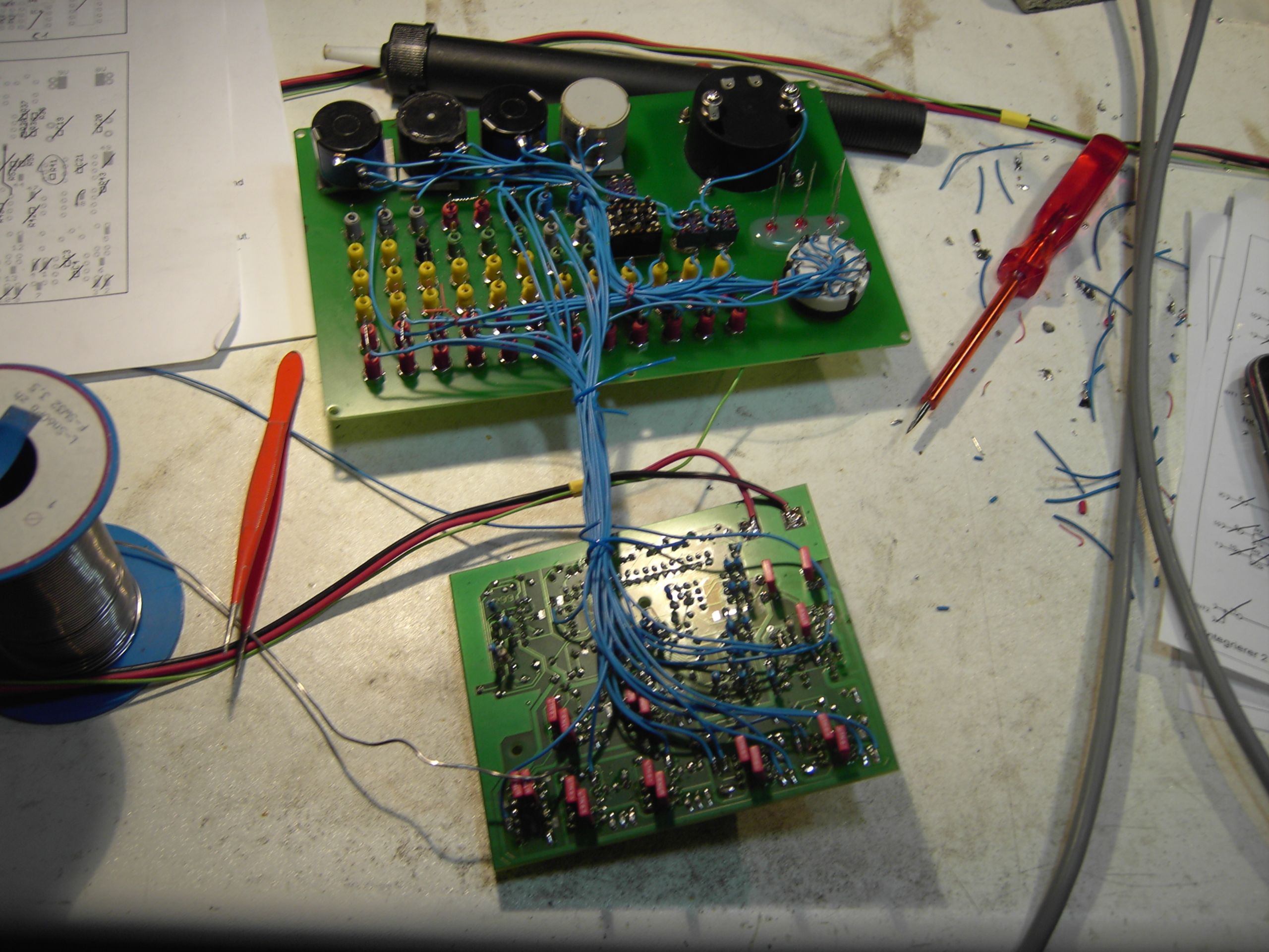
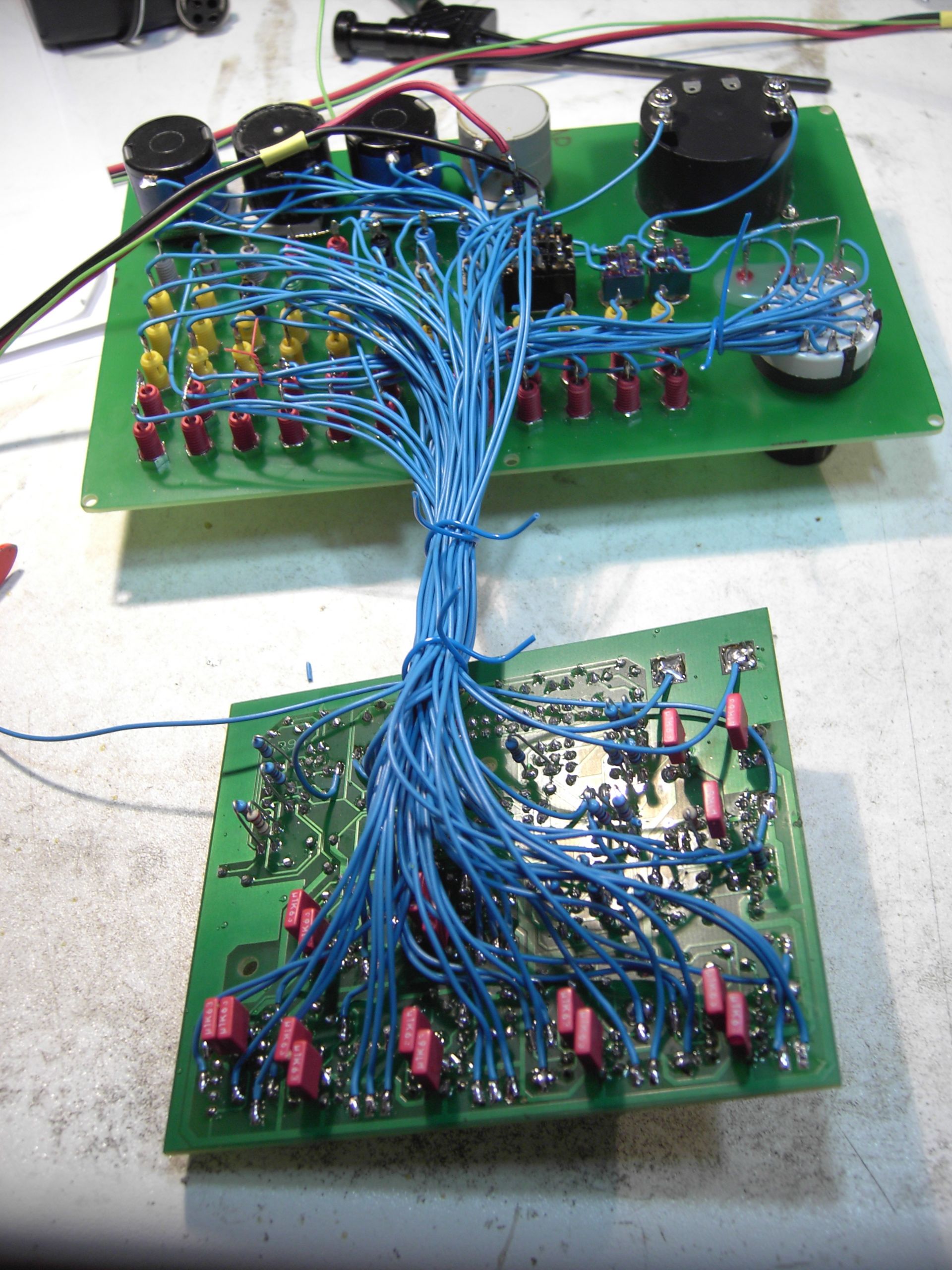
The picture on the right shows an impression of the overall system during assembly. It took more time than expected to solder all the wires but in the end the result looks quite good to me. |
|
|
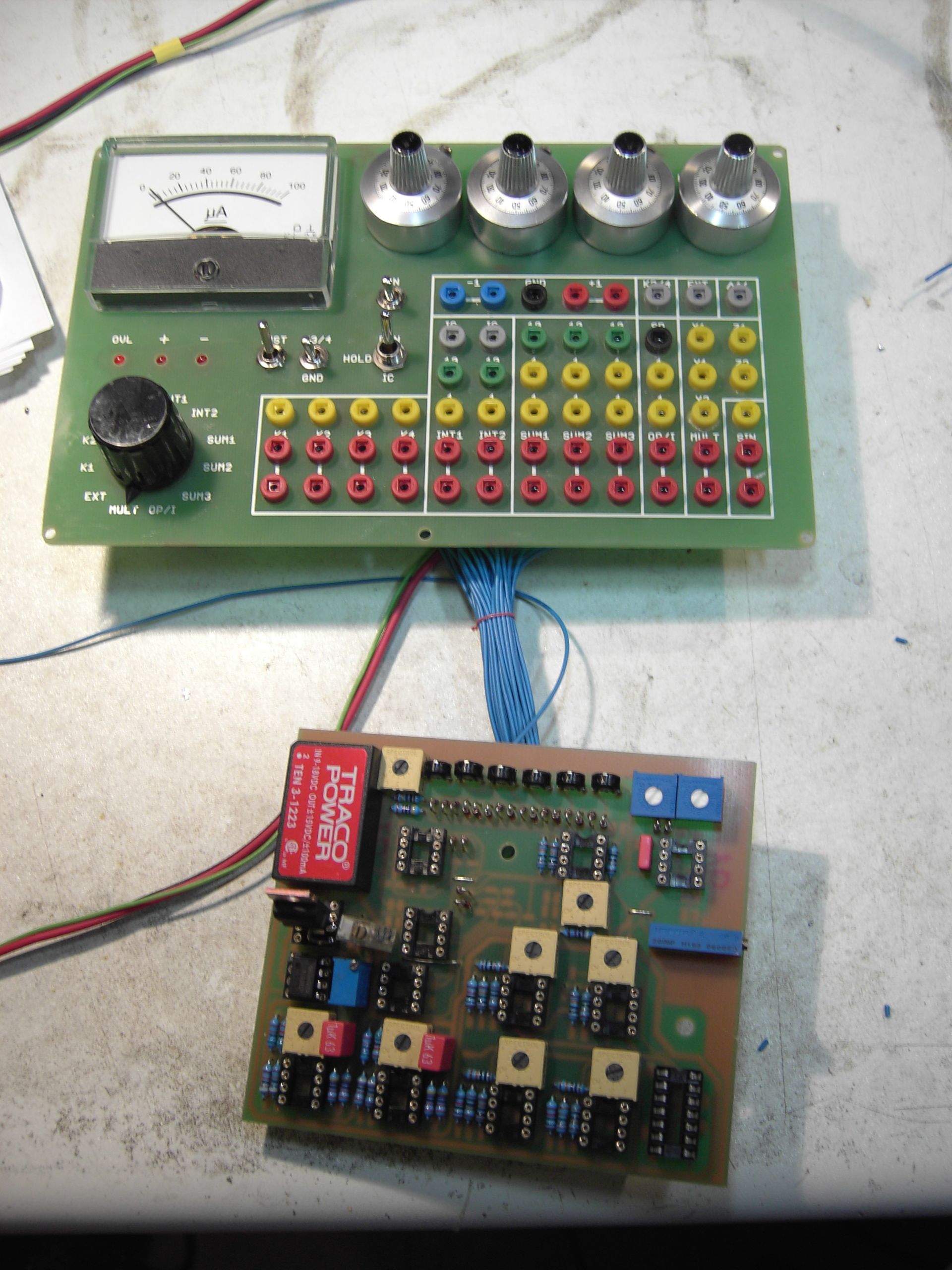
The following pictures show the completed computer without its enclosure and without the ICs fitted into their sockets: |
|
|
|
|
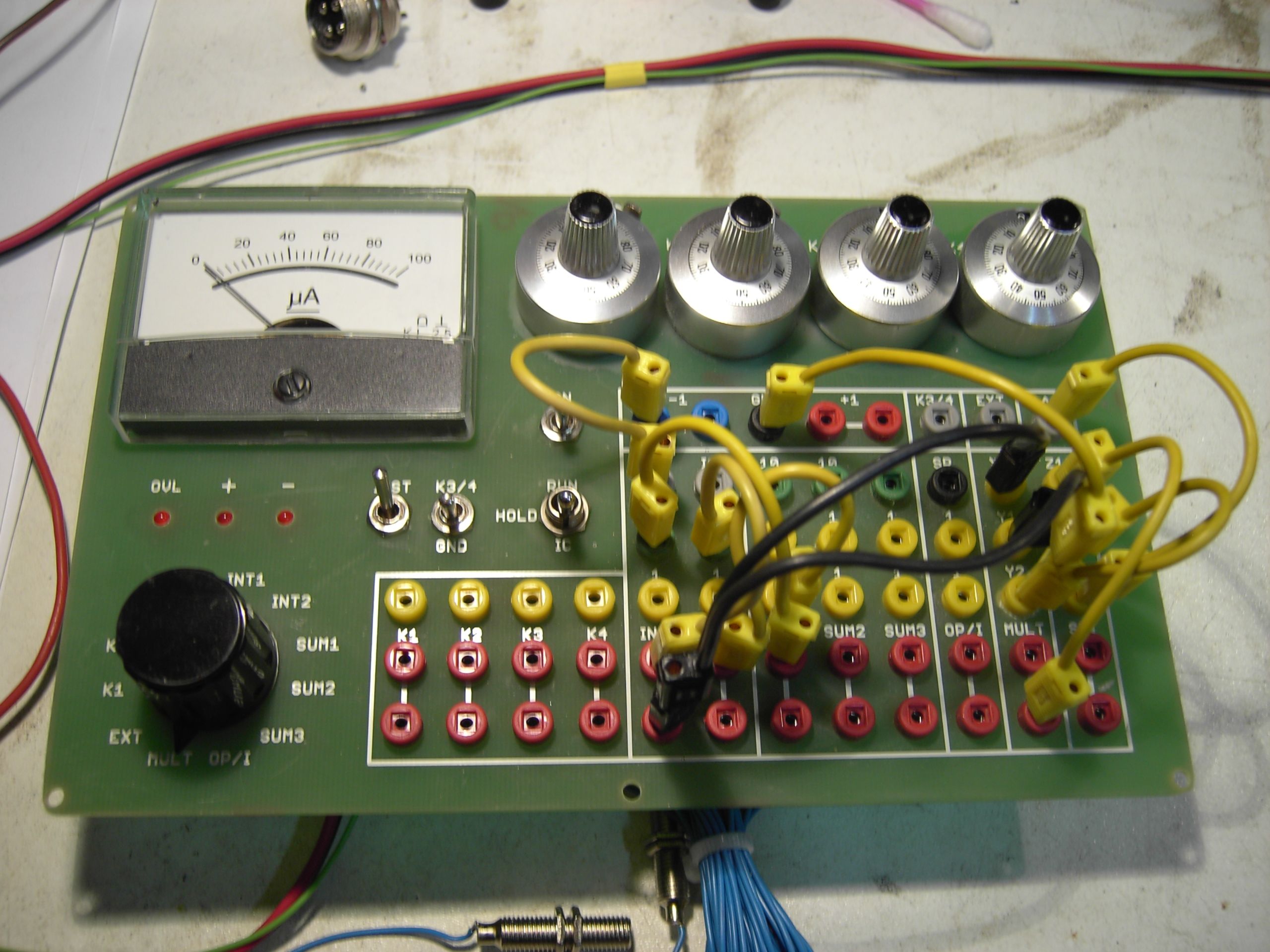
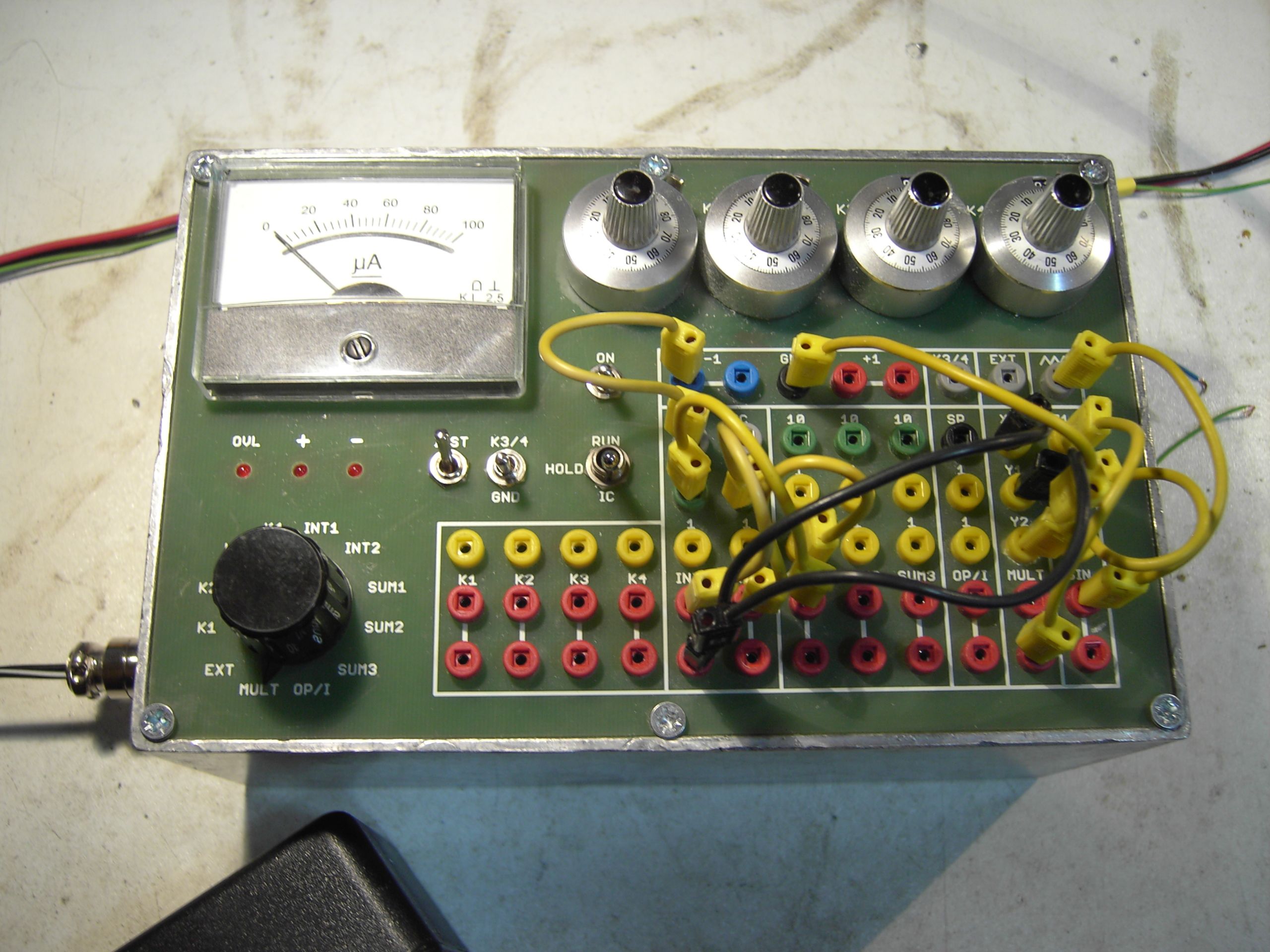
The last two pictures show the completed analog computer with its first test program (this was done after everything was set up - including the sine generator which was quite some work :-) ) - without and with its final enclosure. |
|
|
|
|
This version differs in some respects from the original implementation of Dr. Vogel which is due to the fact that I was unable to get some parts he used. The differences are the following:
|
|