|
A control stick ("joy stick") is a fine instrument - I always wanted to have a control stick for my analog computers since I am interested in man in the loop simulations where some person controls a simulated device like a space craft, a car, etc. Having an analog control stick like the one I used in the following it seems fairly simple to connect it to an analog computer. The longer I thought about it the more subtle problems came to my mind. First of all having only a control stick is not sufficient - some buttons will be needed, too, to control additional functions like switching on a booster rocket or the like. So, I decided to add four buttons to the control stick assembly. To be useful such a control stick needs a rather long cable since the "pilot" may be seated a bit away from the actual analog computer. Having delicate signals running through some meters of cable, together with the rather digital lines for the switches is not a good idea, so I had to decouple the control stick from the signals to be controlled - this required two analog multipliers (AD 633), one for the X- and one for the Y-axis. The same problem came up with the four push buttons - here the solution was fairly simple - the switches control relays which do the actual signal switching with rather short wire lengths. |
|
|
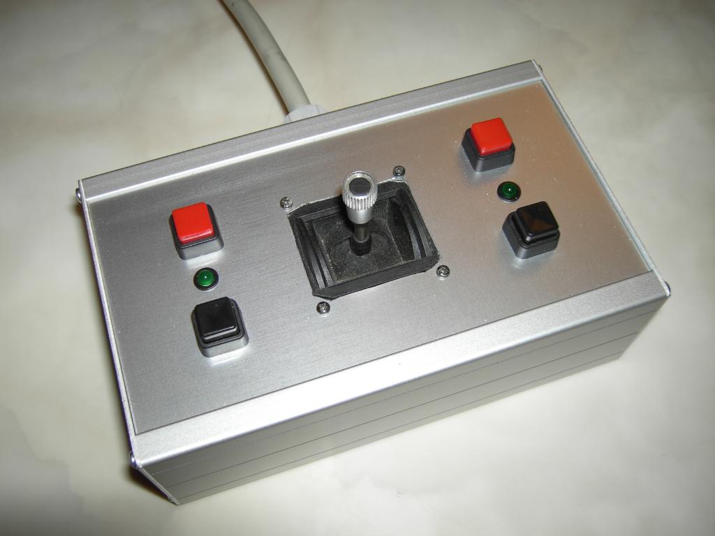
The picture on the right shows the actual control stick assembly. All input elements, i.e. the control stick itself and four switches are mounted in a small aluminium enclosure. The red switches are push buttons which while the black buttons are on/off switches. There is one LED on the right and on the left hand side which can be controlled from the analog computer to give additional feedback information. |
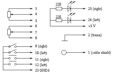
| On the right the schematic of the control stick assembly can be seen. Please note that there are in fact two different ground connections: Analog ground for the cable shield and digital ground used for the aluminium frame. |
|
|
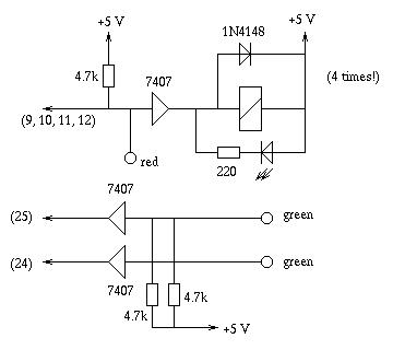
The schematic on the left shows the switch and LED driver circuitry which is housed in the control stick adapter (the rack mountable drawer shown on top of this page). Only one of the four relay drivers is shown. (The 4.7k pull up resistor on the input of the relay driver might have been substituted by a LED with its series resistor thus minimizing the load on the 7407 driver. An arrangement like this would have caused unnecessary large currents in the cable running to the control stick which would have coupled into the analog lines, so it was decided to use this rather conservative circuit.) |
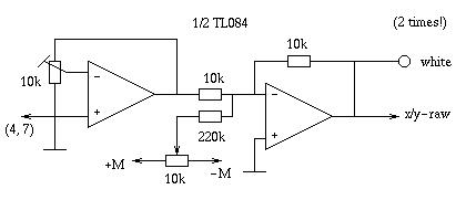
| The drawing on the right shows one of the two input stages which are fed by the wiper of the X- and Y-potentiometers of the control stick. Both potentiometers are connected to +/-M (machine unit = 10 V) - due to the mechanical setup of the control stick, both potentiometer wipers travel only a small fraction of their total way to the output of the potentiometers will not be +/-M at maximum. This is corrected by the first operational amplifier stage which acts as a high impedance, non-inverting amplifier. The second operational amplifier is used for the zero correction of the control stick potentiometer signals - the 10k potentiometer is used to set the output of this amplifier to zero when the control stick is in its home position. |
|
|
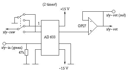
The schematic on the left shows one of the two analog multiplier circuits used in the control stick adapter. The multiplier is an AD 633 - a low precision, cheap device (high precision is not necessary since the control stick and the human controller are by far more inaccurate than anything else in the loop). It receives the raw signal of one of the control stick's axes as well as an input signal fed into the small patch panel on the front plate of the adapter. The DPDT switch can be used to reverse the polarity of the control stick. |
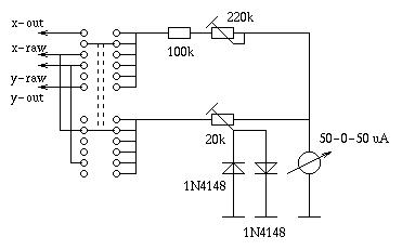
| To facilitate the zero adjustment of the control stick the adapter has a built in zero meter which can be switched to monitor either the X- or the Y-axis. In addition to this the meter can be switched to monitor the output of the multiplier circuits and has a high gain mode for setting accurate zero values. |
|
|
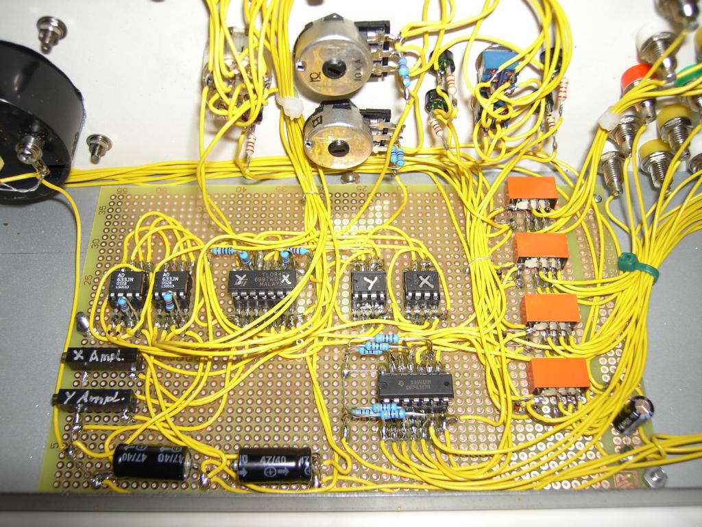
The picture on the left shows the details of the interior of the control stick adapter. The orange devices on the right hand side of the circuit board are the four relays controlled by the four switches. The two ten turn potentiometers on the left are the amplification control potentiometers of the first operational amplifier of the input stage. |
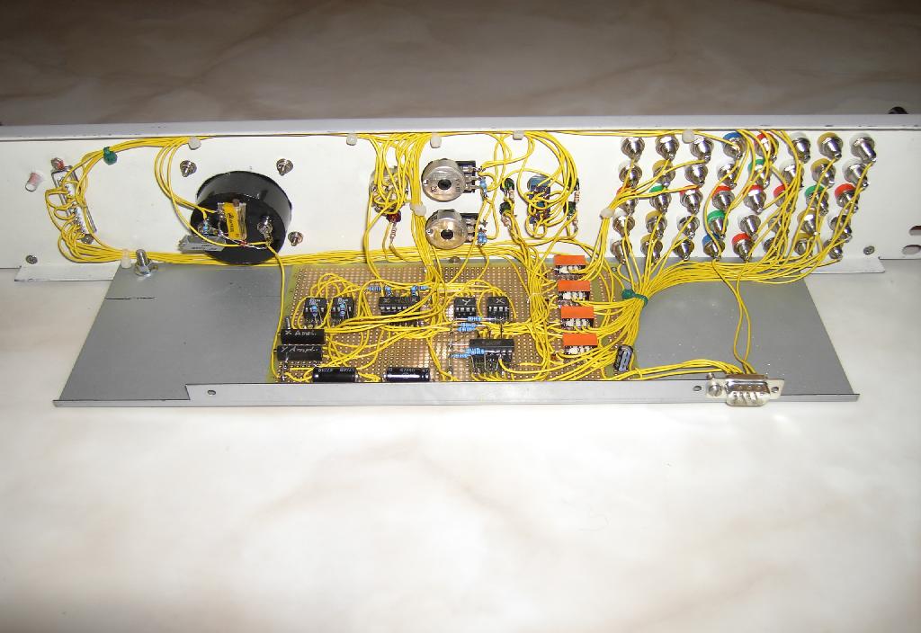
| The picture on the right shows the overall back view of the adapter. |
|
|
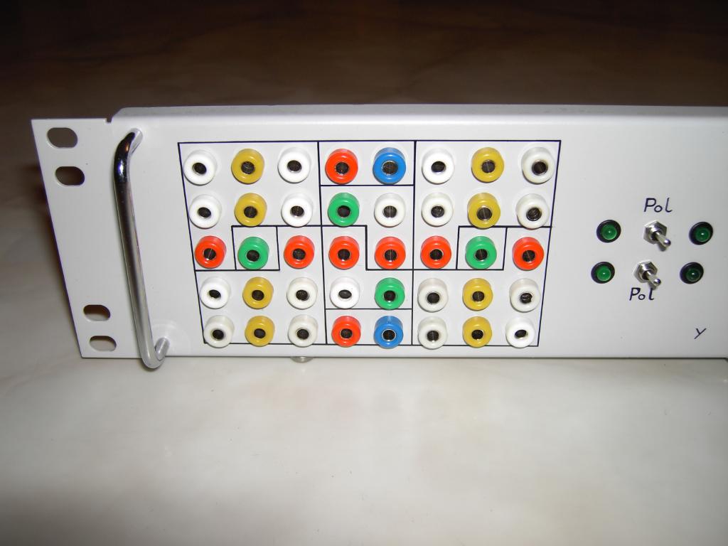
Shown on the left is the patch field of the control stick adapter. It is divided into three main parts (from left to right): The relay outputs and LED control inputs for the switches on the left hand side of the control stick assembly, the analog input/ouput section for the control stick and the relay outputs and LED inputs for the right hand side switches. All in all there are 40 4mm banana jacks. |
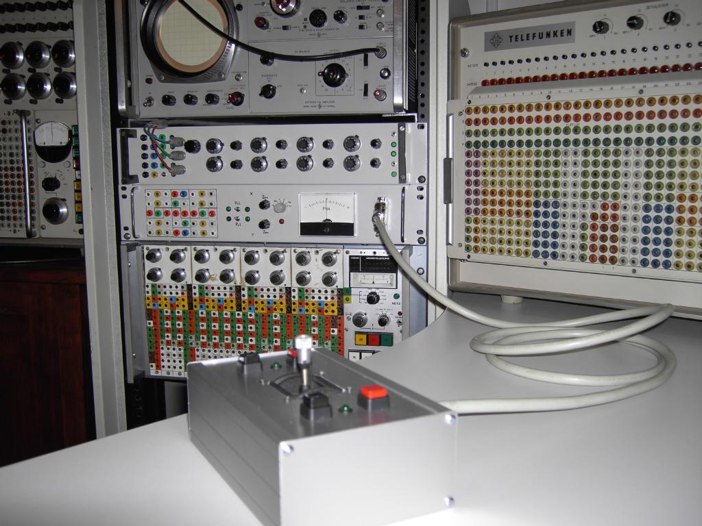
| On the right the adapter can be seen in its natural environment - it is mounted below the four channel X/Y oscilloscope multiplexer and above my Dornier DO-80 analog computer. |
|
|
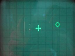
Finally, the picture on the left shows a screen shot from a very simple simulation which I set up as a first proof of concept (this simulation also makes use of the already mentioned four channel X/Y oscilloscope multiplexer). Clicking on the picture will show a short AVI movie (about 5 MB). |