|
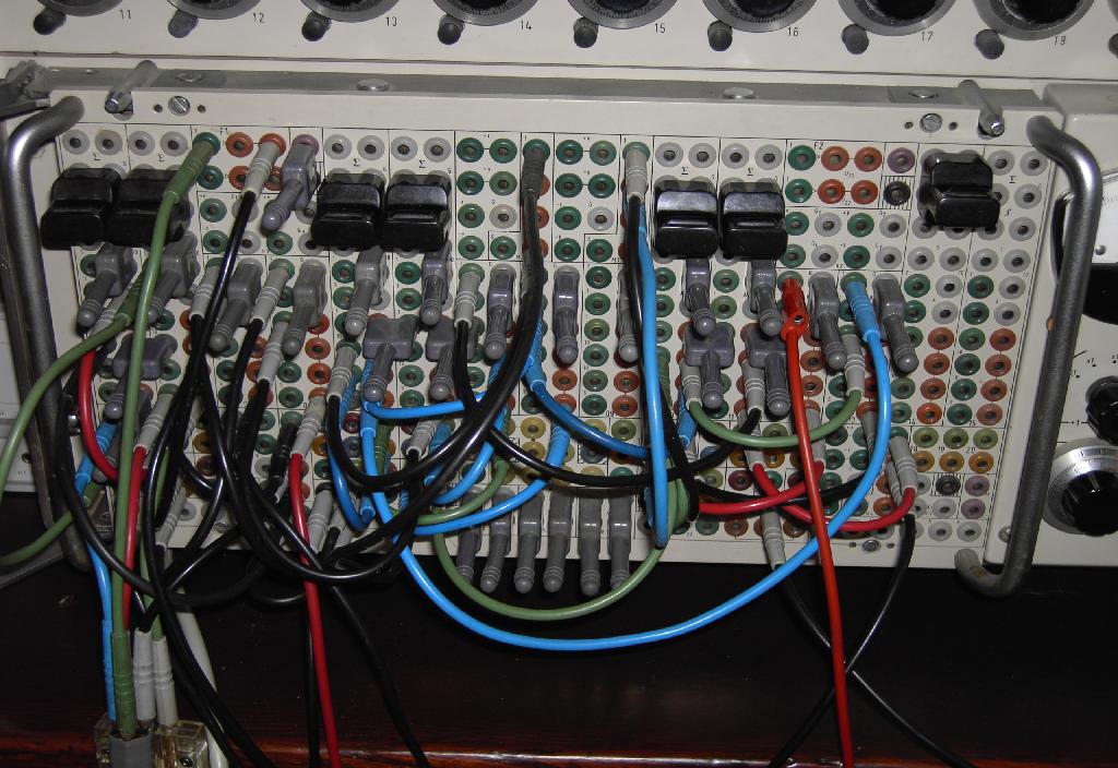
Analog computers are ideally suited to simulate complicated mechanical systems involving several masses, springs and dampers since systems like these can be described conveniently by means of coupled differential equations which is the right food for an analog computer. :-) Several years ago I found the following photograph in an old German magazine called "Hobby", issue 6, 1965: 
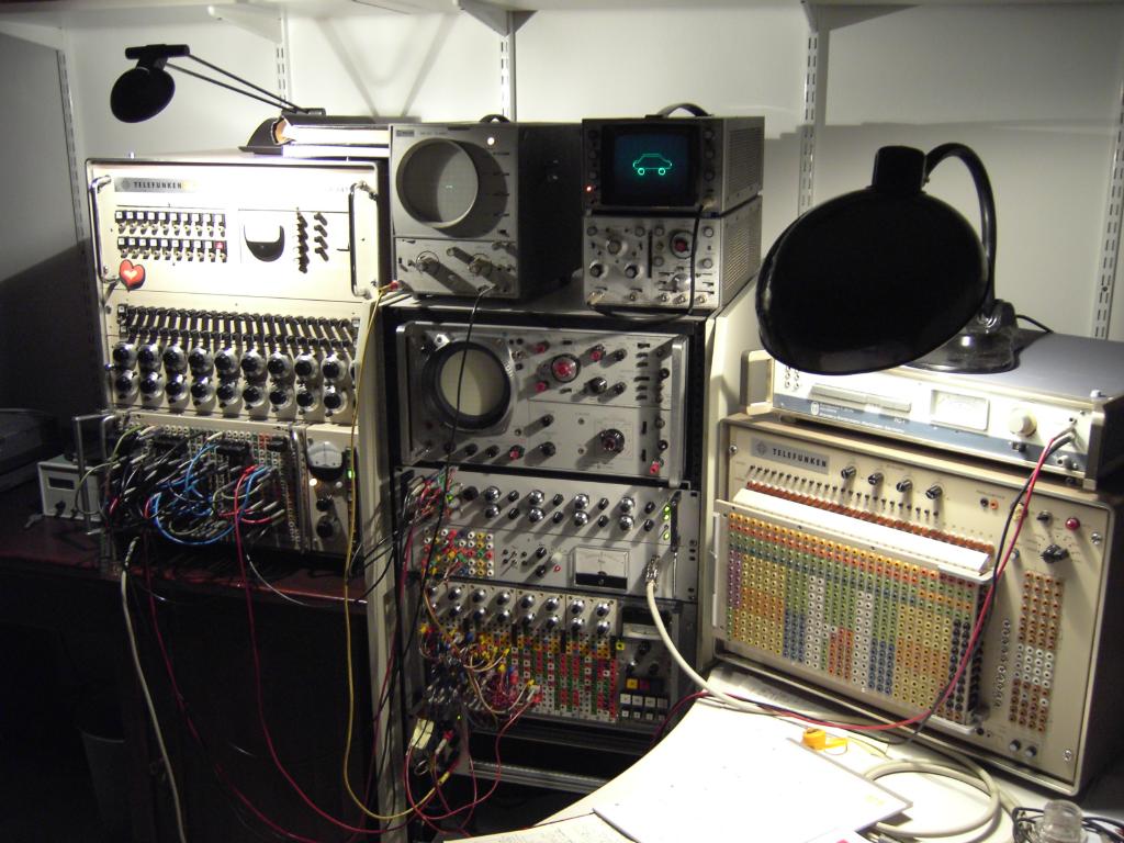
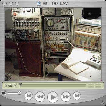
This picture shows the simulation of a (simplified, i.e. involving only two masses, so both wheels are treated as a single, lumped mass) car suspension system which was performed on a Telefunken RAT 700 analog computer (Analogrechner). This particular simulation was developed by Dr. Giloi as a demonstration to promote the then new computer system on a Hannover Messe. It was outstanding to perform such a simulation on a system as small as the RAT 700 (it contains only 15 operational amplifiers). Today I decided to setup such a simulation on one of my Telefunken analog computers (Analogrechner) - in this case a RA 741 was used (this system, fortunately, has some more operational amplifiers than the original machine, Dr. Giloi used (he told me that he employed a trick - the car silhouette was generated by a specialized function generator which occupied one of the four expansion slots of the RAT 700 system thus freeing two operational amplifiers which would have been necessary in conjunction with the standard built in function generator otherwise). The following picture shows the setup of my system for this simulation - please note that not all of the machines shown were actually used - this is just how my recreational area at home looks like. :-) The RA 741 can be seen on the left - it is programmed to display a car frame and two wheels as well as simulate a two mass spring damper system. The rack in the middle of the picture holds on its top two oscilloscopes, the rightmost, a HP-180, is used to display the car. Since this requires a three channel X/Y-oscilloscope, my four channel oscilloscope multiplexer is used (the second drawer from top of the rack). Furthermore the simulation needs a random noise source to simulate a bumpy road, this is done using the Wandel und Goltermann RG-1 on the top right in conjunction with my noise filter.
|
|
|
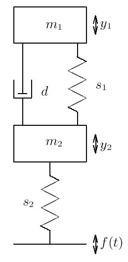
The picture on the left shows the mechanical system which served as the basis to derive the equations describing the automobile suspension system in a form suitable for solving on an electronic analog computer. The mass m1 represents the frame of the car itself which is coupled to the wheels, represented by m2, by means of a spring s1 and a damper d. The wheels are coupled to the road by a spring s2 representing the elasticity of the wheels. |
|
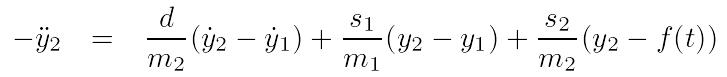
This mechanical system is described by the following two (coupled) differential equations - please note that the movement of the car frame will result in a feedback force to the wheels, too. 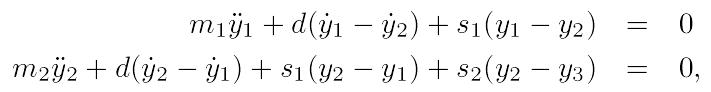
Rearranging these equations will result in 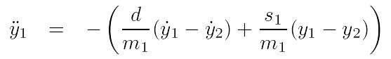
Using Kelvin's feedback method to derive the corresponding circuits to solve these two equations yields 

To create a steady display on an oscilloscope, a stable sine/cosine generator will be needed. It has been (traditionally) implemented by a circuit solving the second order differential equation describing the sine function. To achieve the necessary stability, two Zener diodes were placed into the feedback path of one of the two oscillator integrators. In addition to this a ex characteristic has been added through the coefficient potentiometer denoted by "alpha". The output of the sine/cosine generator is used to draw the wheels while the movement in the y direction is implemented by a summer which will take y2 as one of its inputs (derived by the second partial circuit above). The movement of the car frame is generated the same way by mixing the harmonic signal with the displacement value y1 derived by the first partial circuit shown above. Since it was not desirable to display the car frame as a circle or an ellipsis, a function generator has been employed to transform the harmonic y signal in a way which results in a more car-like envelope. The circuit for the generation of both the wheel and frame figures is shown below - it takes two input signals for the displacement of these two parts from the circuits shown above. 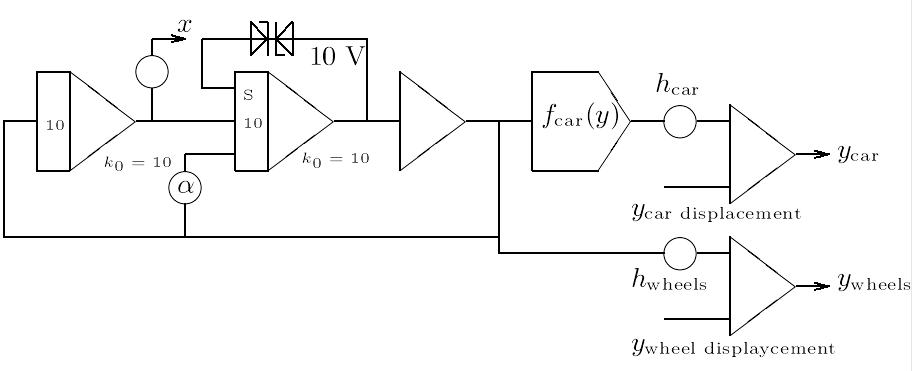
The complete computer circuit is shown below (I would like to thank my wonderful wife Rikka who created this drawing tonight). 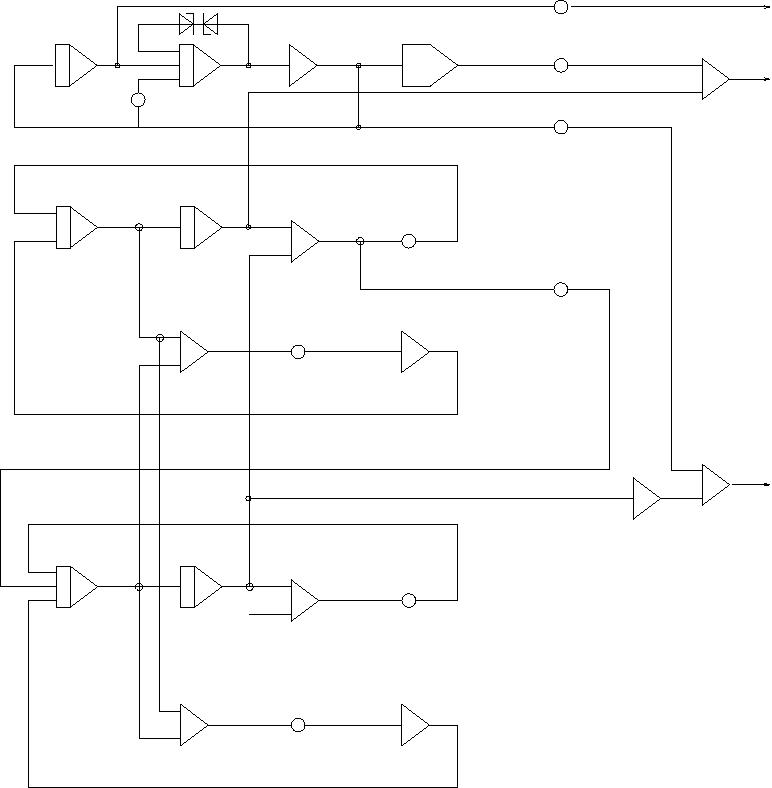
|
|
|
The picture on the left shows the overall program of my car suspension simulation. As you can see, the RA 741 has barely enought operational amplifiers for this program. All in all six integrators, nine summers, one function generator and two free amplifiers (for the function generator) are used. |
|
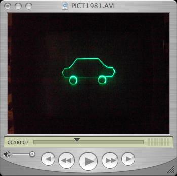
Below you can find three short video clips in AVI format. The left one gives a short impression of the overall setup (the annoying humming sound in the background is caused by the mechanical chopper relais of the Telefunken high gain, drift compensated precision operational amplifiers and some blowers in the rack) - this clip is about 11 MB in size! The following video clip shows the output of the simulation of a car with a rather strong damped suspension system (about 3.5 MB). Since I used to drive a wonderful Chevrolet Caprice Classic when I was studying mathematics at the Universität Mainz, I made a second simulation run with a much weaker damping of the suspension system resembling my long gone Caprice Classic - a video clip (7 MB!) of this simulation can be seen here. |
|
|
|